METER / GAUGE SYSTEM, Diagnostic DTC:B1500
| DTC Code | DTC Name |
|---|---|
| B1500 | Fuel Sender Open Detected |
DESCRIPTION
| DTC No. | Detection Item | DTC Detection Condition | Trouble Area |
|---|---|---|---|
| B1500 | Fuel Sender Open Detected | Both conditions are met:
|
|
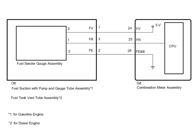
WIRING DIAGRAM
CAUTION / NOTICE / HINT
CAUTION:
Be careful of flames.
Note
When replacing the combination meter assembly, make sure to replace it with a new one.
PROCEDURE
-
READ VALUE USING GTS (FUEL INPUT)
-
Using the GTS, read the Data List.
Body Electrical > Combination Meter > Data ListTester Display Measurement Item Range Normal Condition Diagnostic Note Fuel Input Fuel input Min.: 0, Max.: 127.5 Current fuel level displayed Unit: Liter
Body Electrical > Combination Meter > Data ListTester Display Fuel Input OK Fuel amount value displayed on the GTS is almost the same as the needle indication. Result Proceed to OK NG
OK 
REPLACE COMBINATION METER ASSEMBLY Click here
NG 
-
-
CHECK HARNESS AND CONNECTOR (FUEL GAUGE CIRCUIT)
-
Disconnect the G8 combination meter assembly connector.
-
Disconnect the fuel tank vent tube assembly connector.
-
Measure the resistance according to the value(s) in the table below.
Standard Resistance Tester Connection Condition Specified Condition G8-25 (FR) - O6-3 (FR) Always Below 1 Ω G8-24 (FV) - O6-1 (FV) Always Below 1 Ω G8-26 (FE&B) - O6-2 (FE) Always Below 1 Ω G8-25 (FR) or O6-3 (FR) - Body ground Always 10 kΩ or higher G8-24 (FV) or O6-1 (FV) - Body ground Always 10 kΩ or higher G8-26 (FE&B) or O6-2 (FE) - Body ground Always 10 kΩ or higher Result Proceed to OK NG
NG
REPAIR OR REPLACE HARNESS OR CONNECTOR
OK
-
-
INSPECT FUEL SENDER GAUGE ASSEMBLY
-
Remove the fuel sender gauge assembly.
for 1GR-FE: Click here
for 2TR-FE: Click here
for 1GD-FTV: Click here
for 2GD-FTV: Click here
for 5L-E: Click here
-
Inspect the fuel sender gauge assembly.
for 1GR-FE: Click here
for 2TR-FE: Click here
for 1GD-FTV: Click here
for 2GD-FTV: Click here
for 5L-E: Click here
Result Result Proceed to OK (for Gasoline Engine) A OK (for Diesel Engine) B NG C
B 
INSPECT FUEL TANK VENT TUBE ASSEMBLY Click here
C
REPLACE FUEL SENDER GAUGE ASSEMBLY for 1GR-FE: Click here
REPLACE FUEL SENDER GAUGE ASSEMBLY for 2TR-FE: Click here
REPLACE FUEL SENDER GAUGE ASSEMBLY for 1GD-FTV: Click here
REPLACE FUEL SENDER GAUGE ASSEMBLY for 2GD-FTV: Click here
REPLACE FUEL SENDER GAUGE ASSEMBLY for 5L-E: Click hereA
-
-
INSPECT FUEL SUCTION WITH PUMP AND GAUGE TUBE ASSEMBLY
-
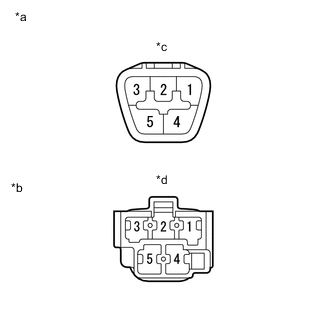
*a Upper Side *b Lower Side
(to Fuel Sender Gauge Assembly)
*c Connector A *d Connector B Remove the fuel suction with pump and gauge tube assembly.
for 1GR-FE: Click here
for 2TR-FE: Click here
-
Measure the resistance according to the value(s) in the table below.
Standard Resistance Tester Connection Condition Specified Condition A-2 - B-2 Always Below 1 Ω A-3 - B-1 Always Below 1 Ω A-1 - B-3 Always Below 1 Ω A-2 - B-1 Always 10 kΩ or higher A-2 - B-3 Always 10 kΩ or higher A-3 - B-3 Always 10 kΩ or higher Result Proceed to OK NG
OK
REPLACE COMBINATION METER ASSEMBLY Click here
NG
REPLACE FUEL SUCTION WITH PUMP AND GAUGE TUBE ASSEMBLY for 1GR-FE: Click here
REPLACE FUEL SUCTION WITH PUMP AND GAUGE TUBE ASSEMBLY for 2TR-FE: Click here -
-
INSPECT FUEL TANK VENT TUBE ASSEMBLY
-
*a Upper Side *b Lower Side
(to Fuel Sender Gauge Assembly)
*c Connector A *d Connector B Remove the fuel tank vent tube assembly.
for 1GD-FTV: Click here
for 2GD-FTV: Click here
for 5L-E: Click here
-
Measure the resistance according to the value(s) in the table below.
Standard Resistance Tester Connection Condition Specified Condition A-2 - B-2 Always Below 1 Ω A-3 - B-1 Always Below 1 Ω A-1 - B-3 Always Below 1 Ω A-2 - B-1 Always 10 kΩ or higher A-2 - B-3 Always 10 kΩ or higher A-3 - B-3 Always 10 kΩ or higher Result Result OK NG
OK
REPLACE COMBINATION METER ASSEMBLY Click here
NG
REPLACE FUEL TANK VENT TUBE ASSEMBLY for 1GD-FTV: Click here
REPLACE FUEL TANK VENT TUBE ASSEMBLY for 2GD-FTV: Click here
REPLACE FUEL TANK VENT TUBE ASSEMBLY for 5L-E: Click here -