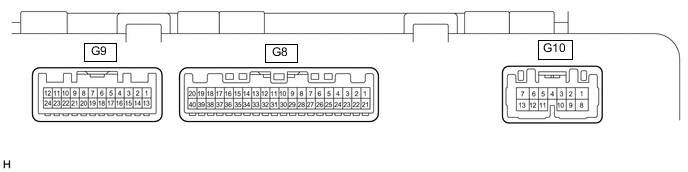
METER / GAUGE SYSTEM TERMINALS OF ECU
-
COMBINATION METER ASSEMBLY
-
Measure the voltage, resistance and waveform according to the value(s) in the table below.
Terminal No. (Symbol) Wiring Color Terminal Description Condition Specified Condition G8-1 (+) - Body ground L - Body ground High beam indicator light signal High beam indicator light on 11 to 14 V High beam indicator light off Below 1 V G8-2 (HEAD) - Body ground R - Body ground Headlight signal Ignition switch ON, headlight dimmer switch tail or head 11 to 14 V Ignition switch ON, headlight dimmer switch off Below 1 V G8-3 (R) - Body ground*11 B - Body ground Revers signal Ignition switch ON, shift lever in R 11 to 14 V Ignition switch ON, shift lever any position other than in R Below 1 V G8-4 (ACAN) - Body ground W - Body ground Dimming signal for other system (Output) Ignition switch ON, automatic light control sensor covered by hand, and light control switch in tail or head position 9 V or higher G8-5 (E1) - Body ground*17 BR - Body ground Ground Always Below 1 Ω G8-8 (CHG-) - Body ground*8 GR - Body ground Charger system warning light signal Ignition switch ON, charger system warning light off 11 to 14 V Ignition switch ON, charger system warning light on Below 1 V G8-9 (VCM) - Body ground*7 Y - Body ground Brake vacuum warning switch signal Ignition switch ON, engine idle speed Pulse generation G8-10 (PKBI) - Body ground V - Body ground Parking brake switch signal Parking brake lever released 11 to 14 V Parking brake lever pulled Below 1 V G8-11 (KSW) - Body ground*4 G - Body ground Unlock warning switch signal No key in ignition key cylinder 11 to 14 V Key in ignition key cylinder Below 1 V G8-12 (FFTR) - Body ground*8 W - Body ground Fuel system warning light signal Ignition switch ON, fuel system warning light off 11 to 14 V Ignition switch ON, fuel system warning light on Below 1 V G8-13 (S) - Body ground*7 G - Body ground Level warning switch signal Ignition switch ON, fuel system warning light off 11 to 14 V Ignition switch ON, fuel system warning light on Below 1 V G8-14 (OIL) - Body ground R - Body ground*5 Engine oil level signal Ignition switch ON, engine oil level low 11 to 14 V Ignition switch ON, engine oil level not low Below 1 V BR - Body ground*6 Ground Always Below 1 Ω G8-15 (S) - Body ground GR - Body ground Engine oil pressure switch signal Ignition switch ON, low engine oil level warning light off 11 to 14 V Ignition switch ON, low engine oil level warning light on Below 1 V G8-16 (SW) - Body ground V - Body ground Brake warning light signal Ignition switch ON, brake warning light off 11 to 14 V Ignition switch ON, brake warning light on Below 1 V G8-18 (SI) - Body ground Y - Body ground Speed signal for other system (Input) Driving at approximately 20 km/h (12 mph) Pulse generation (See waveform) G8-19 (+S) - Body ground V - Body ground Speed signal for other system (Output) Driving at approximately 20 km/h (12 mph) Pulse generation (See waveform) G8-20 (ACAN) - Body ground*3 W - Body ground Dimming signal for other system (Input) Ignition switch ON, automatic light control sensor covered by hand, and light control switch in tail or head position 11 to 14 V Ignition switch ON, automatic light control sensor not covered by hand, and light control switch in auto position Below 1 V G8-20 (ACAN) - Body ground*15 L - Body ground Dimming signal for other system (Input) Ignition switch ON, headlight dimmer switch in tail or head 11 to 14 V Ignition switch ON, headlight dimmer switch off Below 1 V G8-21 (B) - Body ground W - Body ground Battery Always 11 to 14 V G8-22 (IG+) - Body ground Y - Body ground Ignition switch signal Ignition switch ON 11 to 14 V Ignition switch off Below 1 V G8-24 (FV) - Body ground GR - Body ground Fuel sender gauge power source signal Ignition switch ON 4.5 to 5.2 V G8-25 (FR) - Body ground V - Body ground Fuel sender gauge signal Ignition switch ON, fuel level F 4.2 to 4.3 V Ignition switch ON, fuel level E 0.63 to 0.75 V G8-26 (FB&B) - Body ground SB - Body ground Fuel sender gauge ground signal Always Below 1 V G8-27 (EP) - Body ground W-B - Body ground Ground Always Below 1 Ω G9-29 (TIRE) - Body ground*18 R - Body ground Tire pressure warning light signal Ignition switch ON, tire pressure warning light on 0.9 to 3.2 V Ignition switch ON, tire pressure warning light off 3.2 V or higher G8-30 (+DP) - Body ground*14 P - Body ground Steering pad switch signal Ignition switch ON, DISP switch on steering pad switch not pushed 11 to 14 V Ignition switch ON, DISP switch on steering pad switch pushed Below 1 V G8-30 (+DP) - Body ground*13 P - Body ground Steering pad switch signal Ignition switch ON, enter, top and back switches on steering pad switch not pushed 4.3 to 5.2 V Ignition switch ON, enter switch on steering pad switch pushed Below 0.6 V Ignition switch ON, top switch on steering pad switch pushed 1.0 to 2.2 V Ignition switch ON, back switch on steering pad switch pushed 2.3 to 3.4 V G8-31 (+DP2) - Body ground*13 LG - Body ground Steering pad switch signal Ignition switch ON, up, down, right and left switches on steering pad switch assembly not pushed 4.3 to 5.2 V Ignition switch ON, left switch on steering pad switch pushed Below 0.6 V Ignition switch ON, up switch on steering pad switch pushed 1.0 to 2.2 V Ignition switch ON, down switch on steering pad switch pushed 2.3 to 3.4 V Ignition switch ON, right switch on steering pad switch pushed 3.4 to 4.5 V G8-33 (TX1+) - G8-34 (TX1-) SB - G Ambient temperature sensor signal Ambient temperature 25°C (77°F) 1615 to 1785 Ω G8-35 (CANL) - Body ground W - Body ground CAN communication line - - G8-36 (CANH) - Body ground P - Body ground CAN communication line - - G8-37 (LCL-) - Body ground*1, *2 W - Body ground CAN communication line - - G8-38 (LCL+) - Body ground*1, *2 B - Body ground CAN communication line - - G8-39 (ACC) - Body ground GR - Body ground Engine switch signal Engine switch on (ACC) 11 to 14 V Engine switch off Below 1 V G8-40 (TAIL) - Body ground P - Body ground Taillight signal Ignition switch ON, headlight dimmer switch in tail or head 11 to 14 V Ignition switch ON, headlight dimmer switch off Below 1 V G9-1 (FOG) - Body ground*10 P - Body ground Front fog light signal Ignition switch ON, front fog light switch on 11 to 14 V Ignition switch ON, front fog light switch off Below 1 V G9-3 (BKL) - Body ground LG - Body ground Driver side seat belt buckle switch signal Ignition switch ON, driver side seat belt fastened 11 to 14 V Ignition switch ON, driver side seat belt unfastened Below 1 V G9-4 (P/SB) - Body ground W - Body ground Front passenger side seat belt buckle switch signal Ignition switch ON, front passenger side seat belt fastened and front passenger seat occupied 11 to 14 V Ignition switch ON, front passenger side seat belt unfastened and front passenger seat occupied Below 1 V G9-5 (RLBT) - Body ground*12 P - Body ground Rear LH seat belt buckle switch signal Rear LH seat belt unfastened Below 1 V Rear LH seat belt fastened 11 to 14 V G9-6 (RCSB) - Body ground*12 R - Body ground Rear center seat belt buckle switch signal Rear center seat belt unfastened Below 1 V Rear center seat belt fastened 11 to 14 V G9-7 (RRBT) - Body ground*12 SB - Body ground Rear RH seat belt buckle switch signal Rear RH seat belt unfastened Below 1 V Rear RH seat belt fastened 11 to 14 V G9-11 (DRLE) - Body ground*16 G - Body ground Running light relay (DRL) drive output Daytime running light on Below 1 V Daytime running light off 11 to 14 V G9-12 (DOOR) - Body ground Y - Body ground Door courtesy switch signal All doors closed except driver door 11 to 14 V Any door open except driver door Below 1 V G9-13 (S) - Body ground*9 L - Body ground Rear fog light signal Ignition switch ON, rear fog light switch on 11 to 14 V Ignition switch ON, rear fog light switch off Below 1 V G9-15 (DCTY) - Body ground B - Body ground Driver side door condition signal Driver side door closed 11 to 14 V Driver side door open Below 1 V G9-16 (PCTY) - Body ground G - Body ground Front passenger side door condition signal Front passenger side door closed 11 to 14 V Front passenger side door open Below 1 V G9-17 (RLCY) - Body ground V - Body ground Rear door LH condition signal Rear door LH closed 11 to 14 V Rear door LH open Below 1 V G9-18 (RRCY) - Body ground LG - Body ground Rear door RH condition signal Rear door RH closed 11 to 14 V Rear door RH open Below 1 V G9-19 (BDCY) - Body ground B - Body ground Back door condition signal Back door closed 11 to 14 V Back door open Below 1 V G9-20 (GND) - Body ground W-B - Body ground Ground Always Below 1 Ω G9-21 (ILL-) - Body ground*13 W-B - Body ground Illumination signal Ignition switch ON, headlight dimmer switch in tail or head 11 to 14 V Ignition switch ON, headlight dimmer switch off Below 1 V G9-22 (RRMT) - Body ground*12 SB - Body ground Rear RH seat belt warning light signal Rear RH seat belt unfastened Below 1 V Rear RH seat belt fastened 11 to 14 V G9-23 (RCMT) - Body ground*12 GR - Body ground Rear center seat belt fastened Rear center seat belt unfastened Below 1 V Rear center seat belt fastened 11 to 14 V G9-24 (RLMT) - Body ground*12 R - Body ground Rear LH seat belt warning light signal Rear LH seat belt unfastened Below 1 V Rear LH seat belt fastened 11 to 14 V G10-2 (HAZ) - Body ground SB - Body ground Hazard warning signal switch signal (Output) Hazard warning signal switch off 11 to 14 V Hazard warning signal switch on Below 1 V G10-3 (SW) - Body ground R - Body ground Turn signal switch (full turn) signal Headlight dimmer switch off 11 to 14 V Headlight dimmer switch on (full turn) Below 1 V G10-4 (ER) - Body ground P - Body ground RH turn indicator light signal (Input) Ignition switch ON, RH turn signal switch off 11 to 14 V Ignition switch ON, RH turn signal switch on Below 1 V G10-5 (EL) - Body ground BE - Body ground LH turn indicator light signal (Input) Ignition switch ON, LH turn signal switch off 11 to 14 V Ignition switch ON, LH turn signal switch on Below 1 V G10-7 (B) - Body ground L - Body ground Battery Always 11 to 14 V G10-8 (LL) - Body ground Y - Body ground LH turn indicator light signal (Output) Ignition switch ON, LH turn indicator light blinking 11 to 14 V ←→ Below 1 V Ignition switch ON, LH turn indicator light off Below 1 V G10-13 (LR) - Body ground SB - Body ground RH turn indicator light signal (Output) Ignition switch ON, RH turn indicator light blinking 11 to 14 V ←→ Below 1 V Ignition switch ON, RH turn indicator light off Below 1 V *1: w/ Navigation System
*2: w/ Audio and Visual System (for Radio and Display Type)
*3: w/ Automatic Headlight Beam Level Control System
*4: w/o Smart Entry and Start System
*5: for GD Series Engine
*6: for TR Series Engine
*7: for Diesel Engine
*8: for 5L-E
*9: w/ Rear Fog Light
*10: w/ Front Fog Light
*11: for Manual Transmission
*12: w/ Rear Seat Belt Warning
*13: for TFT Display type
*14: for Dot Display type
*15: w/o Automatic Headlight Beam Level Control System
*16: w/ Day Light Runing
*17: for LHD
*18: w/ Tire Pressure Warning System
-
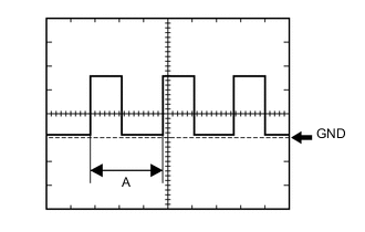
Using an oscilloscope, check waveform.
Waveform (Reference) Item Condition Tester Connection
-
G8-18 (SI) - Body ground
-
G8-19 (+S) - Body ground
Tool setting 5 V/DIV, 20 ms./DIV Vehicle condition Driving at approximately 20 km/h (12 mph) Tech Tips
When the system is functioning normally, one wheel revolution generates 4 pulses. As the vehicle speed increases, the width indicated by (A) in the illustration narrows.
-
-
-