PERSONAL LIGHT(for LED Type) INSPECTION
PROCEDURE
-
INSPECT MAP LIGHT ASSEMBLY (PERSONAL LIGHT)
-
Inspect the map light switch.
-
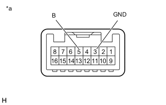
*a Component without harness connected
(Map Light Assembly (Personal Light))
Measure the resistance according to the value(s) in the table below.
Standard Resistance Tester Connection Switch Condition Specified Condition 5 (B) - 3 (GND) Map light switch LH OFF, RH OFF 10 kΩ or higher Map light switch LH ON, RH OFF Below 1 Ω Map light switch LH ON, RH ON Below 1 Ω Map light switch LH OFF, RH ON Below 1 Ω If the result is not as specified, replace the map light assembly (personal light).
-
-
Inspect the courtesy switch.
-
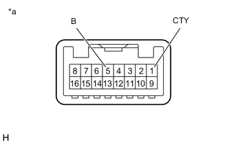
*a Component without harness connected
(Map Light Assembly (Personal Light))
Measure the resistance according to the value(s) in the table below.
Standard Resistance Tester Connection Switch Condition Specified Condition 5 (B) - 1 (CTY) Courtesy switch OFF 10 kΩ or higher Courtesy switch ON Below 1 Ω If the result is not as specified, replace the map light assembly (personal light).
-
-
Inspect the telephone microphone circuit.
-
Disconnect the telephone microphone assembly connector.
-
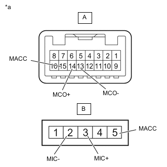
*a Component without harness connected
(Map Light Assembly (Personal Light))
Measure the resistance according to the value(s) in the table below.
Standard Resistance Tester Connection Switch Condition Specified Condition A15 (MACC) - B5 (MACC) Always Below 1 Ω A14 (MCO+) - B3 (MIC+) Always Below 1 Ω A13 (MCO-) - B2 (MIC-) Always Below 1 Ω If the result is not as specified, replace the map light assembly (personal light).
-
-
Inspect the map light.
-
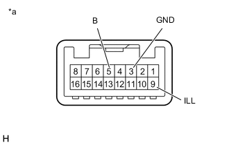
*a Component without harness connected
(Map Light Assembly (Personal Light))
Apply battery voltage to the connector and check the light illumination condition.
OK Tester Connection Switch Condition Specified Condition Battery positive (+) → 5 (B)
Battery negative (-) → 3 (GND)
Map light switch LH ON Map light LH illuminates Map light switch RH ON Map light RH illuminates Battery positive (+) → 9 (ILL)
Battery negative (-) → 3 (GND)
Always Switch illuminates If the result is not as specified, replace the map light assembly (personal light).
-
-