LIGHTING SYSTEM TERMINALS OF ECU
-
CHECK INSTRUMENT PANEL JUNCTION BLOCK ASSEMBLY AND BODY ECU
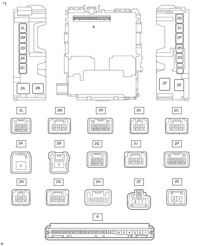
*1 Instrument Panel Junction Block Assembly - - 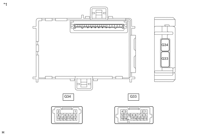
*1 Body ECU - -
-
Remove the body ECU from the instrument panel junction block assembly.
-
Measure the voltage and resistance according to the value(s) in the table below.
Terminal No. (Symbol) Wiring Color Terminal Description Condition Specified Condition A-6 (BECU) - Body ground - Battery power supply Always 11 to 14 V A-7 (IG) - Body ground - IG power supply Ignition switch ON 11 to 14 V*1 10.5 to 16 V*2 A-1 (GND) - Body ground - Ground Always Below 1 Ω *1: w/o Stop and Start System
*2: w/ Stop and Start System
-
Install the body ECU to the instrument panel junction block assembly.
-
Measure the voltage and check for pulses according to the value(s) in the table below.
Terminal No. (Symbol) Wiring Color Terminal Description Condition Specified Condition 2Q-9 (ILE) - Body ground B - Body ground Illumination signal Map light, spot light and No. 1 room light switch in DOOR position and map light assembly, sot light assembly and No. 1 room light assembly come on Below 1 V Map light, spot light and No. 1 room light switch in DOOR position and map light assembly, spot light and No. 1 room light assembly go off 11 to 14 V 2L-4 (DCTY) - Body ground R - Body ground Front door courtesy light switch assembly RH signal Front door RH open Below 1 V Front door RH closed Pulse generation G33-14 (PCTY) - Body ground LG - Body ground Front door courtesy light switch assembly LH signal Front door LH open Below 1 V Front door LH closed Pulse generation G33-15 (LSWD) - Body ground R - Body ground Front door RH unlock detection switch signal Front door RH locked Pulse generation Front door RH unlocked Below 1 V G33-8 (KSW) - Bodyground*1 G - Body ground Unlock warningswitch assemblysignal No key in ignitionkey cylinder Pulse generation Key in ignition keycylinder Below 1 V G33-9 (PRG) - Body ground*2 V - Body ground Signal output to certification ECU (smart key ECU assembly) Ignition switch off, all doors closed, 10 seconds elapsed after all doors locked and electrical key transmitter sub-assembly unlock switch not pressed 11 to 14 V Ignition switch off, all doors closed, 10 seconds elapsed after all doors locked and electrical key transmitter sub-assembly unlock switch pressed Pulse generation 2Q-2 (ACTY) - Body ground Y - Body ground Door courtesy switch signal All doors closed except driver door Pulse generation Any door opened except driver door Below 1 V 2P-13 (DOMR) - Body ground L - Body ground Battery saving control (interior light auto cut function) signal Battery saving control (interior light auto cut function) operating 11 to 14 V Battery saving control (interior light auto cut function) not operating Below 1.7 V G33-16 (RDA) - Body ground*2 W - Body ground Signal input from certification ECU (smart key ECU assembly) Ignition switch off, all doors closed, 10 seconds elapsed after all doors locked and electrical key transmitter sub-assembly unlock switch not pressed 11 to 14 V Ignition switch off, all doors closed, 10 seconds elapsed after all doors locked and electrical key transmitter sub-assembly unlock switch pressed Pulse generation G33-2 (LSWP) - Body ground Y - Body ground Door unlock detection switch input (except front door RH) Except front door RH unlocked Below 1 V Except front door RH locked Pulse generation *1: w/o Smart Entry and Start System
*2: w/ Smart Entry and Start System
-
-
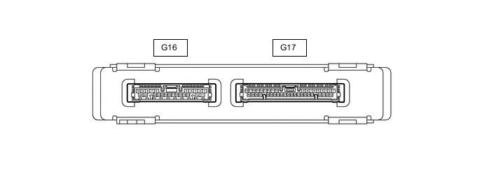
CHECK CERTIFICATION ECU (SMART KEY ECU ASSEMBLY) (w/ Smart Entry and Start System)
-
Disconnect the G16 certification ECU (smart key ECU assembly) connector.
-
Measure the voltage and resistance according to the value(s) in the table below.
Tech Tips
Measure the values on the wire harness side with the connectors disconnected.
Terminal No. (Symbol) Wiring Color Terminal Description Condition Specified Condition G16-1 (+B) - Body ground P - Body ground Battery power supply Always 11 to 14 V G16-10 (E) - Body ground BR - Body ground Ground Always Below 1 Ω -
Reconnect the G16 certification ECU (smart key ECU assembly) connector.
-
Measure the voltage and check for pulses according to the value(s) in the table below.
Terminal No. (Symbol) Wiring Color Terminal Description Condition Specified Condition G16-19 (SWIL) - G16-24 (AGND) G - SB Engine switch illumination drive output Engine switch illumination on 9 to 14 V Engine switch illumination off Below 1 V G16-9 (LSWP) - G16-10 (E) L - BR Door unlock detection switch input (except front door RH) Engine switch off, all doors closed, all doors unlocked and electrical key transmitter sub-assembly lock switch not pressed Below 1 V Engine switch off, all doors closed, all doors unlocked and electrical key transmitter sub-assembly lock switch pressed 8.5 V or higher G17-13 (RDA3) - G16-10 (E) W - BR Signal output to body ECU Engine switch off, all doors closed, 10 seconds elapsed after all doors locked and electrical key transmitter sub-assembly unlock switch not pressed 11 to 14 V Engine switch off, all doors closed, 10 seconds elapsed after all doors locked and electrical key transmitter sub-assembly unlock switch pressed Pulse generation G17-36 (PRG3) - G16-10 (E) V - BR Signal input from body ECU Engine switch off, all doors closed, 10 seconds elapsed after all doors locked and electrical key transmitter sub-assembly unlock switch not pressed 11 to 14 V Engine switch off, all doors closed, 10 seconds elapsed after all doors locked and electrical key transmitter sub-assembly unlock switch pressed Pulse generation G16-21 (ACCD) - G16-10 (E) B - BR ACC signal Engine switch off → Engine switch ACC 1 V or less → 8.5 V or higher G16-20 (IG1D) - G16-10 (E) L - BR IG1 signal Engine switch ACC → Engine switch on (IG) 1 V or less → 9 V or higher
-