THEFT DETERRENT SYSTEM Unlock Warning Switch Circuit
DESCRIPTION
The unlock warning switch assembly comes on when the ignition key is inserted into the ignition key cylinder and goes off when the ignition key is removed.
WIRING DIAGRAM
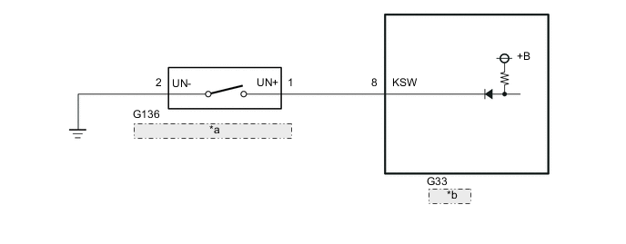
| *a | Unlock Warning Switch Assembly |
| *b | Body ECU |
CAUTION / NOTICE / HINT
Note
-
Inspect the fuses for circuits related to this system before performing the following procedure.
-
If the body ECU has been replaced, it is necessary to initialize the body ECU.
PROCEDURE
-
INSPECT UNLOCK WARNING SWITCH ASSEMBLY
-
Remove the unlock warning switch assembly.
-
Inspect the unlock warning switch assembly.
Result Proceed to OK NG
NG 
REPLACE UNLOCK WARNING SWITCH ASSEMBLY Click here
OK 
-
-
CHECK HARNESS AND CONNECTOR (UNLOCK WARNING SWITCH ASSEMBLY - BODY ECU AND BODY GROUND)
-
Disconnect the G33 body ECU connector.
-
Disconnect the G136 unlock warning switch assembly connector.
-
Measure the resistance according to the value(s) in the table below.
Standard Resistance Tester Connection Condition Specified Condition G33-8 (KSW) - G136-1 Always Below 1 Ω G33-8 (KSW) - Body ground Always 10 kΩ or higher G136-1 - Body ground Always 10 kΩ or higher G136-2 - Body ground Always Below 1 Ω Result Result OK NG
OK
REPLACE BODY ECU Click here
NG
REPAIR OR REPLACE HARNESS OR CONNECTOR
-