THEFT DETERRENT SYSTEM ECU Power Source Circuit
DESCRIPTION
This circuit provides power to operate the body ECU.
WIRING DIAGRAM
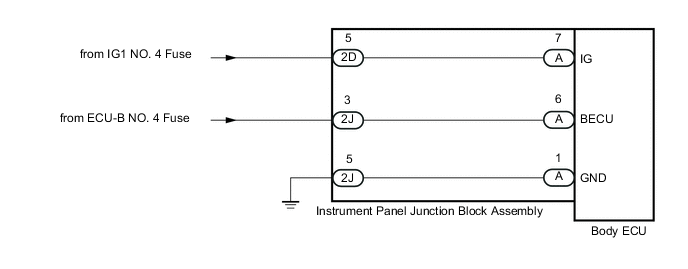
CAUTION / NOTICE / HINT
Note
-
Inspect the fuses for circuits related to this system before performing the following procedure.
-
If the body ECU has been replaced, it is necessary to initialize the body ECU.
PROCEDURE
-
CHECK HARNESS AND CONNECTOR (POWER SOURCE CIRCUIT)
-
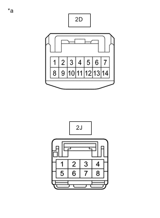
*a Front view of wire harness connector
(to Instrument Panel Junction Block Assembly)
Disconnect the instrument panel junction block assembly connectors.
-
Measure the resistance according to the value(s) in the table below.
Standard Resistance Tester Connection Condition Specified Condition 2J-5 - Body ground Always Below 1 Ω -
Measure the voltage according to the value(s) in the table below.
Standard Voltage Tester Connection Condition Specified Condition 2D-5 - Body ground Ignition switch ON 11 to 14 V 2J-3 - Body ground Always 11 to 14 V Result Proceed to OK NG
NG 
REPAIR OR REPLACE HARNESS OR CONNECTOR
OK 
-
-
INSPECT INSTRUMENT PANEL JUNCTION BLOCK ASSEMBLY
-
Remove the body ECU.
-
Measure the resistance according to the value(s) in the table below.
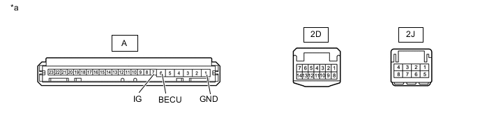
*a Component without harness connected
(Instrument Panel Junction Block Assembly)
- - Standard Resistance Tester Connection Switch Condition Specified Condition 2J-5 - A-1 (GND) Always Below 1 Ω 2D-5 - A-7 (IG) Always Below 1 Ω 2J-3 - A-6 (BECU) Always Below 1 Ω Result Proceed to OK NG
OK
PROCEED TO NEXT SUSPECTED AREA SHOWN IN PROBLEM SYMPTOMS TABLE Click here
NG
REPLACE INSTRUMENT PANEL JUNCTION BLOCK ASSEMBLY Click here
-