THEFT DETERRENT SYSTEM Glass Breakage Sensor Circuit
DESCRIPTION
When the glass breakage sensor detects that the back door glass, rear door quarter window glass LH or RH is tapped or broken, the sensor will set off the alarm for 30 seconds.
WIRING DIAGRAM
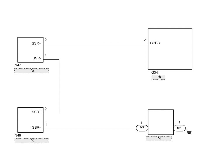
| *a | Rear Door Quarter Window Glass RH |
| *b | Body ECU |
| *c | Rear Door Quarter Window Glass LH |
| *d | Back Door Glass |
CAUTION / NOTICE / HINT
Note
-
w/ Door control Battery:
As the door control battery is installed between the vehicle battery and body ECU, first perform the inspections to confirm that there are no malfunctions in the power source circuit for the body ECU before performing this troubleshooting procedure.
-
w/ Automatic Light Control System:
If the body ECU has been replaced, it is necessary to initialize the body ECU.
PROCEDURE
-
CHECK HARNESS AND CONNECTOR (BODY ECU - GLASS BREAKAGE SENSOR AND BODY GROUND)
-
Disconnect the G34 body ECU connector.
-
Disconnect the N47, N48, b2 and b3 glass breakage sensor connectors.
-
Measure the resistance according to the value(s) in the table below.
Standard Resistance Tester Connection Condition Specified Condition G34-2 (GPBS) - N47-2 (SSR+) Always Below 1 Ω N47-1 (SSR-) - N48-2 (SSR+) Always Below 1 Ω N48-1 (SSR-) - b3-1 Always Below 1 Ω b2-1 - Body ground Always Below 1 Ω G34-2 (GPBS) - Body ground Always 10 kΩ or higher N47-2 (SSR+) - Body ground Always 10 kΩ or higher N47-1 (SSR-) - Body ground Always 10 kΩ or higher N48-2 (SSR+) - Body ground Always 10 kΩ or higher N48-1 (SSR-) - Body ground Always 10 kΩ or higher b3-1 - Body ground Always 10 kΩ or higher Result Proceed to OK NG
NG 
REPAIR OR REPLACE HARNESS OR CONNECTOR
OK 
-
-
INSPECT REAR DOOR QUARTER WINDOW GLASS RH
-
Disconnect the N47 rear door quarter window glass RH connector.
-

Measure the resistance according to the value(s) in the table below.
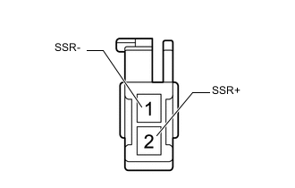
Standard Resistance Tester Connection Condition Specified Condition 2 (SSR+) - 1 (SSR-) Always Below 1 Ω Result Proceed to OK NG
NG
REPLACE REAR DOOR QUARTER WINDOW GLASS RH Click here
OK
-
-
INSPECT REAR DOOR QUARTER WINDOW GLASS LH
-
Disconnect the N48 rear door quarter window glass LH connector.
-
Measure the resistance according to the value(s) in the table below.
Standard Resistance Tester Connection Condition Specified Condition 2 (SSR+) - 1 (SSR-) Always Below 1 Ω Result Proceed to OK NG
NG
REPLACE REAR DOOR QUARTER WINDOW GLASS LH Click here
OK
-
-
INSPECT BACK DOOR GLASS
-
Disconnect the b3 and b2 back door glass connectors.
-
Measure the resistance according to the value(s) in the table below.
Standard Resistance Tester Connection Condition Specified Condition b3-1 - b2-1 Always Below 1 Ω Result Proceed to OK NG
OK
REPLACE BODY ECU for LHD: Click here for RHD: Click here
NG
REPLACE BACK DOOR GLASS Click here
-