THEFT DETERRENT SYSTEM Security Indicator Light Circuit
DESCRIPTION
When the theft deterrent system is in the disarmed state, the security indicator light does not illuminate. When the theft deterrent system is in the armed state, the body ECU blinks the security indicator light continuously.
When the theft deterrent system is in the arming preparation state or alarm sounding state, the body ECU illuminates the security indicator light.
WIRING DIAGRAM
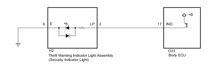
CAUTION / NOTICE / HINT
PROCEDURE
-
CHECK HARNESS AND CONNECTOR (THEFT WARNING INDICATOR LIGHT ASSEMBLY - BODY ECU AND BODY GROUND)
-
Disconnect the H2 theft warning indicator light assembly connector.
-
Disconnect the G33 body ECU connector.
-
Measure the resistance according to the value(s) in the table below.
Standard Resistance Tester Connection Condition Specified Condition H2-2 (LP) - G33-17 (IND) Always Below 1 Ω H2-2 (LP) - Body ground Always 10 kΩ or higher G33-17 (IND) - Body ground Always 10 kΩ or higher H2-6 (E) - Body ground Always Below 1 Ω Result Proceed to OK NG
NG 
REPAIR OR REPLACE HARNESS OR CONNECTOR
OK 
-
-
INSPECT THEFT WARNING INDICATOR LIGHT ASSEMBLY
-
Remove the theft warning indicator light assembly.
-
Inspect the theft warning indicator light assembly.
Result Proceed to OK NG
OK
PROCEED TO NEXT SUSPECTED AREA SHOWN IN PROBLEM SYMPTOMS TABLE Click here
NG
REPLACE THEFT WARNING INDICATOR LIGHT ASSEMBLY Click here
-