LIGHTING SYSTEM, Diagnostic DTC:B2430, B2431
| DTC Code | DTC Name |
|---|---|
| B2430 | LED Headlight LH |
| B2431 | LED Headlight RH |
DESCRIPTION
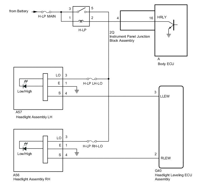
The illumination of the low beam headlights is controlled by the body ECU. When the headlights are turned on, the headlight leveling ECU assembly receives a signal from the headlight assembly and detects the illumination condition of the low beam headlights.
| DTC No. | Detection Item | DTC Detection Condition | Trouble Area |
|---|---|---|---|
| B2430 | LED Headlight LH | Low beam headlight LH malfunction |
|
| B2431 | LED Headlight RH | Low beam headlight RH malfunction |
|
Tech Tips
DTC B2430 and B2431 are not output if 12 seconds have not elapsed since the ignition switch was turned to ON.
WIRING DIAGRAM
CAUTION / NOTICE / HINT
Note
-
Inspect the fuses for circuits related to this system before performing the following procedure.
-
If the headlight leveling ECU assembly has been replaced, it is necessary to initialize the headlight leveling ECU assembly.
-
When replacing the headlight leveling ECU assembly, be sure to initialize the automatic light control system.
Tech Tips
If DTC B2416 and/or B241A (Automatic Headlight Beam Level Control System) is output at the same time as DTC B2430 and/or B2431, perform troubleshooting for DTC B2416 and/or B241A (Automatic Headlight Beam Level Control System) first.
PROCEDURE
-
CLEAR DTC
-
Clear the DTCs.
Body Electrical > HL AutoLeveling > Clear DTCsResult Proceed to NEXT
NEXT 
-
-
CHECK FOR DTC
-
Check for DTCs.
Body Electrical > HL AutoLeveling > Trouble CodesResult Result Proceed to DTC B2430 and B2431 are not output. A DTC B2430 and B2431 are output. B DTC B2430 or B2431 is output. C
A 
USE SIMULATION METHOD TO CHECK Click here
C 
CHECK HARNESS AND CONNECTOR (HEADLIGHT RELAY [H-LP] - HEADLIGHT ASSEMBLY) Click here
B
-
-
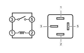
INSPECT HEADLIGHT RELAY (H-LP)
-
Remove the headlight relay (H-LP) from the engine room relay block assembly.
-
Measure the resistance according to the value(s) in the table below.
Standard Resistance Tester Connection Condition Specified Condition 3 - 5 Battery voltage not applied between terminals 1 and 2 10 kΩ or higher 3 - 5 Battery voltage applied between terminals 1 and 2 Below 1 Ω Result Proceed to OK NG
NG
REPLACE HEADLIGHT RELAY (H-LP)
OK
-
-
CHECK HARNESS AND CONNECTOR (HEADLIGHT RELAY [H-LP] - BATTERY)
-
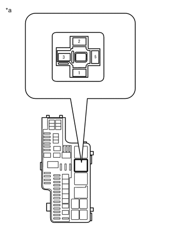
*a Front view of wire harness connector
(to Headlight Relay [H-LP])
Remove the headlight relay (H-LP) from the engine room relay block assembly.
-
Measure the voltage according to the value(s) in the table below.
Standard Voltage Tester Connection Condition Specified Condition Headlight relay (H-LP) terminal 3 - Body ground Always 11 to 14 V Headlight relay (H-LP) terminal 1 - Body ground Always 11 to 14 V Result Proceed to OK NG
NG
REPAIR OR REPLACE HARNESS OR CONNECTOR
OK
-
-
CHECK HARNESS AND CONNECTOR (HEADLIGHT RELAY [H-LP] - HEADLIGHT ASSEMBLY)
-
Remove the headlight relay (H-LP) from the engine room relay block assembly.
-
Disconnect the A57*1 or A56*2 headlight assembly connector.
-
*1: for LH Side
-
*2: for RH Side
-
-
Measure the resistance according to the value(s) in the table below.
Standard Resistance Tester Connection Condition Specified Condition Headlight relay (H-LP) terminal 5 - A57-3 (LO)*1 Always Below 1 Ω Headlight relay (H-LP) terminal 5 - A56-3 (LO)*2 Always Below 1 Ω Headlight relay (H-LP) terminal 5 - Body ground Always 10 kΩ or higher Result Proceed to OK NG
NG
REPAIR OR REPLACE HARNESS OR CONNECTOR
OK
-
-
CHECK HARNESS AND CONNECTOR (HEADLIGHT RELAY [H-LP] - INSTRUMENT PANEL JUNCTION BLOCK ASSEMBLY)
-
Remove the headlight relay (H-LP) from the engine room relay block assembly.
-
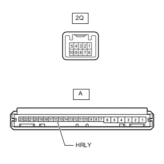
Disconnect the 2Q instrument panel junction block assembly connector.
-
Measure the resistance according to the value(s) in the table below.
Standard Resistance Tester Connection Condition Specified Condition Headlight relay (H-LP) terminal 2 - 2Q-4 Always Below 1 Ω Headlight relay (H-LP) terminal 2 - Body ground Always 10 kΩ or higher Result Proceed to OK NG
NG
REPAIR OR REPLACE HARNESS OR CONNECTOR
OK
-
-
INSPECT INSTRUMENT PANEL JUNCTION BLOCK ASSEMBLY
-
Remove the instrument panel junction block assembly.
-
Remove the body ECU from the instrument panel junction block assembly.
-
Measure the resistance according to the value(s) in the table below.
Standard Resistance Tester Connection Condition Specified Condition A-16 (HRLY) - 2Q-4 Always Below 1 Ω Result Result OK NG
NG
REPLACE INSTRUMENT PANEL JUNCTION BLOCK ASSEMBLY Click here
OK
-
-
CHECK BODY ECU
-
Disconnect the A57*1 or A56*2 headlight assembly connector.
-
*1: for LH Side
-
*2: for RH Side
-
-
Measure the voltage according to the value(s) in the table below.
Standard Voltage Tester Connection Condition Specified Condition A57-3 (LO) - Body ground Headlight dimmer switch (light control switch) in head position 11 to 14 V Result Proceed to OK NG
OK
REPLACE HEADLIGHT LEVELING ECU ASSEMBLY Click here
NG
REPLACE BODY ECU Click here
-
-
CHECK HARNESS AND CONNECTOR (HEADLIGHT RELAY [H-LP] - HEADLIGHT ASSEMBLY)
-
Remove the headlight relay (H-LP) from the engine room relay block assembly.
-
Disconnect the A57*1 or A56*2 headlight assembly connector.
-
*1: for LH Side
-
*2: for RH Side
-
-
Measure the resistance according to the value(s) in the table below.
Standard Resistance for LH Side (B2430) Tester Connection Condition Specified Condition Headlight relay (H-LP) terminal 5 - A57-3 (LO) Always Below 1 Ω Headlight relay (H-LP) terminal 5 - Body ground Always 10 kΩ or higher for RH Side (B2431) Tester Connection Condition Specified Condition Headlight relay (H-LP) terminal 5 - A56-3 (LO) Always Below 1 Ω Headlight relay (H-LP) terminal 5 - Body ground Always 10 kΩ or higher Result Proceed to OK NG
NG
REPAIR OR REPLACE HARNESS OR CONNECTOR
OK
-
-
CHECK HARNESS AND CONNECTOR (HEADLIGHT ASSEMBLY - HEADLIGHT LEVELING ECU ASSEMBLY AND BODY GROUND)
-
Disconnect the A57*1 or A56*2 headlight assembly connector.
-
*1: for LH Side
-
*2: for RH Side
-
-
Disconnect the G40 headlight leveling ECU assembly connector.
-
Measure the resistance according to the value(s) in the table below.
Standard Resistance for LH Side (B2430) Tester Connection Condition Specified Condition A57-4 (S) - G40-3 (LLEW) Always Below 1 Ω A57-1 (E) - Body ground Always Below 1 Ω A57-4 (S) - Body ground Always 10 kΩ or higher for RH Side (B2431) Tester Connection Condition Specified Condition A56-4 (S) - G40-2 (RLEW) Always Below 1 Ω A56-1 (E) - Body ground Always Below 1 Ω A56-4 (S) - Body ground Always 10 kΩ or higher Result Proceed to OK NG
NG
REPAIR OR REPLACE HARNESS OR CONNECTOR
OK
-
-
CHECK RH HEADLIGHT ASSEMBLY
-
Temporarily replace the headlight assembly with a new or normally functioning one.
-
Check for DTCs.
Body Electrical > HL AutoLeveling > Trouble CodesResult Result Proceed to DTC B2430 and B2431 are not output. A DTC B2430 or B2431 is output. B
A
END (HEADLIGHT ASSEMBLY WAS DEFECTIVE)
B
REPLACE HEADLIGHT LEVELING ECU ASSEMBLY Click here
-