THEFT DETERRENT SYSTEM Horn Circuit
DESCRIPTION
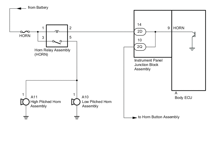
When the theft deterrent system is switched from the armed state to the alarm sounding state, the body ECU transmits a signal to cause the horn to sound at intervals of 0.4 seconds.
WIRING DIAGRAM
CAUTION / NOTICE / HINT
Note
-
Inspect the fuses for circuits related to this system before performing the following procedure.
-
If the body ECU has been replaced, it is necessary to initialize the body ECU.
PROCEDURE
-
INSPECT HORN
-
Press the horn switch and check if the horn sounds.
Result Result Proceed to Horn sounds A Horn does not sound B
B 
GO TO HORN SYSTEM Click here
A 
-
-
INSPECT INSTRUMENT PANEL JUNCTION BLOCK ASSEMBLY
-
Remove the body ECU.
-
Disconnect the instrument panel junction block assembly connector.
-
Measure the resistance according to the value(s) in the table below.
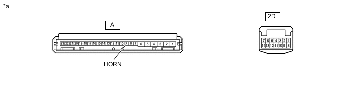
*a Component without harness connected (Instrument Panel Junction Block Assembly) - - Standard Resistance Tester Connection Condition Specified Condition 2D-14 - A-9 (HORN) Always Below 1 Ω Result Proceed to OK NG
OK
REPLACE BODY ECU Click here
NG
REPLACE INSTRUMENT PANEL JUNCTION BLOCK ASSEMBLY Click here
-