THEFT DETERRENT SYSTEM Engine Hood Courtesy Switch Circuit
DESCRIPTION
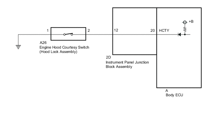
The engine hood courtesy switch is installed together with the hood lock. This switch turns on when the engine hood is closed and turns off when the engine hood is opened.
WIRING DIAGRAM
CAUTION / NOTICE / HINT
PROCEDURE
-
INSPECT ENGINE HOOD COURTESY SWITCH (HOOD LOCK ASSEMBLY)
-
Remove the engine hood courtesy switch (hood lock assembly).
-
Inspect the engine hood courtesy switch (hood lock assembly).
Result Proceed to OK NG
NG 
REPLACE ENGINE HOOD COURTESY SWITCH (HOOD LOCK ASSEMBLY) Click here
OK 
-
-
CHECK HARNESS AND CONNECTOR (ENGINE HOOD COURTESY SWITCH (HOOD LOCK ASSEMBLY) - INSTRUMENT PANEL JUNCTION BLOCK ASSEMBLY AND BODY GROUND)
-
Disconnect the A26 engine hood courtesy switch (hood lock assembly) connector.
-
Disconnect the 2D instrument panel junction block assembly connector.
-
Measure the resistance according to the value(s) in the table below.
Standard Resistance Tester Connection Condition Specified Condition A26-2 - 2D-12 Always Below 1 Ω A26-2 - Body ground Always 10 kΩ or higher 2D-12 - Body ground Always 10 kΩ or higher A26-1 - Body ground Always Below 1 Ω Result Proceed to OK NG
NG
REPAIR OR REPLACE HARNESS OR CONNECTOR
OK
-
-
INSPECT INSTRUMENT PANEL JUNCTION BLOCK ASSEMBLY
-
Remove the body ECU.
-
Disconnect the instrument panel junction block assembly connector.
-
Measure the resistance according to the value(s) in the table below.
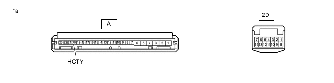
*a Component without harness connected (Instrument Panel Junction Block Assembly) - - Standard Resistance Tester Connection Condition Specified Condition 2D-12 - A-20 (HCTY) Always Below 1 Ω Result Proceed to OK NG
OK
REPLACE BODY ECU Click here
NG
REPLACE INSTRUMENT PANEL JUNCTION BLOCK ASSEMBLY Click here
-