SMART ENTRY AND START SYSTEM(for Entry Function) Entry Exterior Alarm and Answer-back Buzzer do not Sound
DESCRIPTION
The smart entry and start system (for Entry Function) uses the wireless door lock buzzer to perform various vehicle exterior warnings.
WIRING DIAGRAM
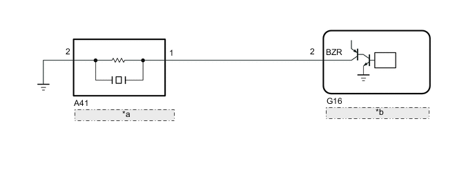
| *a | Wireless Door Lock Buzzer |
| *b | Certification ECU (Smart Key ECU Assembly) |
CAUTION / NOTICE / HINT
Note
-
The smart entry and start system (for Entry Function) uses the LIN communication system and CAN communication system. Inspect the communication function by following How to Proceed with Troubleshooting. Troubleshoot the entry and start system (for Entry Function) after confirming that the communication systems are functioning properly.
-
When using the GTS with the engine switch off, connect the GTS to the DLC3 and turn a courtesy light switch on and off at intervals of 1.5 seconds or less until communication between the GTS and the vehicle begins. Then select Model Code "KEY REGIST" under manual mode and enter the following menus: Body Electrical / Entry&Start(CAN). While using the GTS, periodically turn a courtesy light switch on and off at intervals of 1.5 seconds or less to maintain communication between the GTS and the vehicle.
-
Before replacing the certification ECU (smart key ECU assembly), refer to smart entry and start system (for Entry Function) Precaution.
-
After repair, confirm that no DTCs are output by performing "DTC Output Confirmation Operation".
-
If the body ECU has been replaced, it is necessary to initialize the body ECU.
PROCEDURE
-
CHECK WIRELESS DOOR LOCK CONTROL SYSTEM
-
Check that the wireless door lock functions operate normally.
Result Result Proceed to Wireless door lock function operates normally A Wireless door lock function does not operate normally B
B 
GO TO WIRELESS DOOR LOCK CONTROL SYSTEM Click here
A 
-
-
PERFORM ACTIVE TEST USING GTS (WIRELESS BUZZER)
-
Connect the GTS to the DLC3.
-
Turn the engine switch on (IG).
-
Turn the GTS on.
-
Enter the following menus: Body Electrical / Entry&Start / Active Test.
-
Perform the Active Test according to the display on the GTS.
Body Electrical > Entry&Start > Active TestTester Display Measurement Item Control Range Diagnostic Note Wireless Buzzer Operation Wireless door lock buzzer OFF/ON -
Body Electrical > Entry&Start > Active TestTester Display Wireless Buzzer Operation Result Result Proceed to Wireless door lock buzzer does not turn on/off. A Wireless door lock buzzer turns on/off. B
B
REPLACE CERTIFICATION ECU (SMART KEY ECU ASSEMBLY)
A
-
-
CHECK HARNESS AND CONNECTOR (WIRELESS DOOR LOCK BUZZER - CERTIFICATION ECU [SMART KEY ECU ASSEMBLY] AND BODY GROUND)
-
Disconnect the A41 wireless door lock buzzer connector.
-
Disconnect the G16 certification ECU (smart key ECU assembly) connector.
-
Measure the resistance according to the value(s) in the table below.
Standard Resistance Tester Connection Condition Specified Condition A41-1 - G16-2 (BZR) Always Below 1 Ω A41-2 - Body ground Always Below 1 Ω A41-1 or G16-2 (BZR) - Body ground Always 10 kΩ or higher Result Proceed to OK NG
NG
REPAIR OR REPLACE HARNESS OR CONNECTOR
OK
-
-
REPLACE WIRELESS DOOR LOCK BUZZER
-
Replace the wireless door lock buzzer with a new or known good one.
Result Proceed to NEXT
NEXT
-
-
PERFORM ACTIVE TEST USING GTS (WIRELESS BUZZER)
-
Connect the GTS to the DLC3.
-
Turn the engine switch on (IG).
-
Turn the GTS on.
-
Enter the following menus: Body Electrical / Entry&Start / Active Test.
-
Perform the Active Test according to the display on the GTS.
Body Electrical > Entry&Start > Active TestTester Display Measurement Item Control Range Diagnostic Note Wireless Buzzer Operation Wireless door lock buzzer OFF/ON -
Body Electrical > Entry&Start > Active TestTester Display Wireless Buzzer Operation Result Result Proceed to Wireless door lock buzzer does not turn on/off. A Wireless door lock buzzer turns on/off. B
A
REPLACE CERTIFICATION ECU (SMART KEY ECU ASSEMBLY)
B
END (WIRELESS DOOR LOCK BUZZER WAS DEFECTIVE)
-