REAR DOOR LOCK REMOVAL
CAUTION / NOTICE / HINT
The necessary procedures (adjustment, calibration, initialization or registration) that must be performed after parts are removed, installed or replaced during the rear door lock removal/installation are shown below.
| Replacement Part or Procedure | Necessary Procedures | Effects / Inoperative when not Performed | Link |
|---|---|---|---|
| Disconnect cable from negative battery terminal |
w/ Power Back Door System: |
Power back door system |
Tech Tips
-
Use the same procedure for the RH and LH sides.
-
The procedure listed below is for the RH side.
-
Fully open the rear door glass sub-assembly RH before proceeding with work.
PROCEDURE
-
PRECAUTION
Note
After turning the ignition switch off, waiting time may be required before disconnecting the cable from the negative (-) battery terminal. Therefore, make sure to read the disconnecting the cable from the negative (-) battery terminal notice before proceeding with work.
-
DISCONNECT CABLE FROM NEGATIVE BATTERY TERMINAL
Note
When disconnecting the cable, some systems need to be initialized after the cable is reconnected.
-
REMOVE REAR DOOR FRAME GARNISH RH
-
REMOVE REAR ARMREST ASSEMBLY RH
-
REMOVE REAR POWER WINDOW REGULATOR SWITCH ASSEMBLY WITH REAR DOOR ARMREST BASE PANEL
-
REMOVE REAR DOOR INSIDE HANDLE BEZEL PLUG RH
-
REMOVE REAR DOOR TRIM BOARD SUB-ASSEMBLY RH
-
REMOVE REAR DOOR SERVICE HOLE COVER RH
-
REMOVE REAR DOOR GLASS RUN RH
-
REMOVE REAR DOOR WINDOW DIVISION BAR SUB-ASSEMBLY RH
-
REMOVE REAR DOOR GLASS SUB-ASSEMBLY RH
-
REMOVE REAR DOOR LOCK CHILD PROTECTION COVER RH
-
REMOVE REAR DOOR LOCK ASSEMBLY RH
-
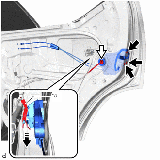
*a Release Plate 
"Torx" Screw 
Connector 
Remove in this Direction Disconnect the connector.
-
Using a T30 "TORX" socket wrench, remove the 3 screws.
-
Slide the rear door lock assembly RH downward, and pull the release plate out of the rear door outside handle frame sub-assembly RH.
-
-
REMOVE REAR DOOR LOCK COVER SUB-ASSEMBLY RH
-

Protective Tape Using a thin-bladed screwdriver, detach the claw and clamp and remove the rear door lock cover sub-assembly RH from the rear door lock assembly RH.
Tech Tips
Tape the thin-bladed screwdriver tip before use.
-
-
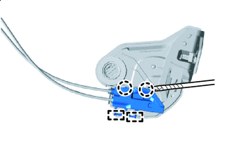
REMOVE REAR DOOR LOCK REMOTE CONTROL CABLE ASSEMBLY RH
-
Remove in this Direction Detach the guide and remove the rear door lock remote control cable assembly RH from the rear door lock assembly RH.
-
-
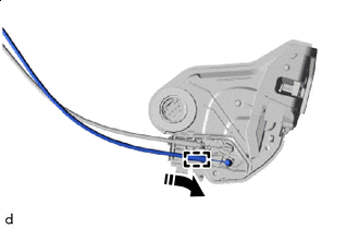
REMOVE REAR DOOR INSIDE LOCKING CABLE ASSEMBLY RH
-
Remove in this Direction Detach the guide and remove the rear door inside locking cable assembly RH from the rear door lock assembly RH.
-
-
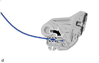
REMOVE DOOR LOCK WIRING HARNESS SEAL
-
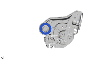
Remove the door lock wiring harness seal from the rear door lock assembly RH.
-