FRONT DOOR LOCK REMOVAL
CAUTION / NOTICE / HINT
The necessary procedures (adjustment, calibration, initialization or registration) that must be performed after parts are removed, installed or replaced during the front door lock removal/installation are shown below.
| Replacement Part or Procedure | Necessary Procedures | Effects / Inoperative when not Performed | Link |
|---|---|---|---|
| Disconnect cable from negative battery terminal |
w/ Power Back Door System: |
Power back door system |
Tech Tips
-
Use the same procedure for the RH and LH sides.
-
The procedure listed below is for the RH side.
-
Fully open the front door glass sub-assembly RH before proceeding with work.
PROCEDURE
-
PRECAUTION
Note
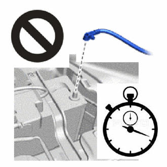
After turning the ignition switch off, waiting time may be required before disconnecting the cable from the negative (-) battery terminal. Therefore, make sure to read the disconnecting the cable from the negative (-) battery terminal notice before proceeding with work.
-
DISCONNECT CABLE FROM NEGATIVE BATTERY TERMINAL
CAUTION:
-
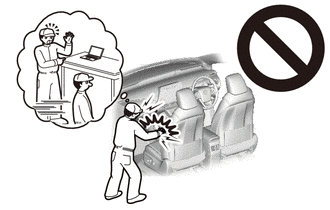
Wait at least 90 seconds after disconnecting the cable from the negative (-) battery terminal to disable the SRS system.
-
If the airbag deploys for any reason, it may cause a serious accident.
Note
When disconnecting the cable, some systems need to be initialized after the cable is reconnected.
-
-
REMOVE FRONT DOOR LOWER FRAME BRACKET GARNISH RH
-
REMOVE FRONT ARMREST ASSEMBLY RH
-
REMOVE POWER WINDOW REGULATOR MASTER SWITCH ASSEMBLY WITH FRONT DOOR ARMREST BASE PANEL (for Driver Side)
-
REMOVE POWER WINDOW REGULATOR SWITCH ASSEMBLY WITH FRONT DOOR ARMREST BASE PANEL (for Front Passenger Side)
-
REMOVE FRONT DOOR INSIDE HANDLE BEZEL PLUG RH
-
REMOVE FRONT DOOR TRIM BOARD SUB-ASSEMBLY RH
-
REMOVE FRONT DOOR SERVICE HOLE COVER RH
-
REMOVE FRONT DOOR GLASS RUN RH
-
REMOVE FRONT DOOR GLASS SUB-ASSEMBLY RH
-
REMOVE FRONT DOOR REAR LOWER FRAME SUB-ASSEMBLY RH
-
REMOVE FRONT DOOR OUTSIDE HANDLE COVER WITH LOCK CYLINDER ASSEMBLY (for Driver Side)
-
REMOVE FRONT DOOR LOCK ASSEMBLY RH
-
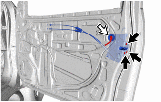

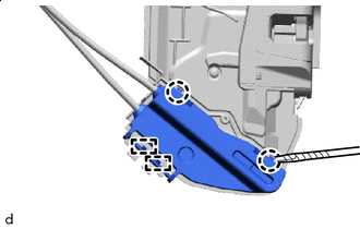
"Torx" Screw 
Connector Disconnect the connector.
-
Using a T30 "TORX" socket wrench, remove the 3 screws.
-
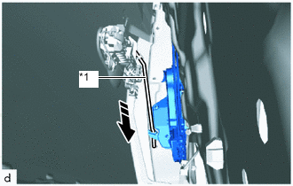
*1 front door lock open rod RH 
Remove in this Direction Disconnect the front door lock open rod RH and remove the front door lock assembly RH as shown in the illustration.
-
-
REMOVE FRONT DOOR LOCK COVER SUB-ASSEMBLY RH
-

Protective Tape Using a thin-bladed screwdriver, detach the claw and clamp and remove the front door lock cover sub-assembly RH from the front door lock assembly RH.
Tech Tips
Tape the thin-bladed screwdriver tip before use.
-
-
REMOVE FRONT DOOR INSIDE LOCKING CABLE ASSEMBLY RH
-
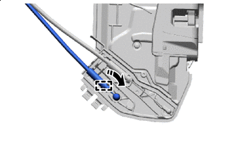
Remove in this Direction Detach the guide and remove the front door inside locking cable assembly RH from the front door lock assembly RH.
-
-
REMOVE FRONT DOOR LOCK REMOTE CONTROL CABLE ASSEMBLY RH
-
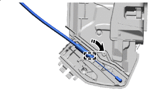
Remove in this Direction Detach the guide and remove the front door lock remote cable assembly RH from the front door lock assembly RH.
-
-
REMOVE DOOR LOCK WIRING HARNESS SEAL
-
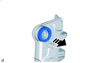
Remove in this Direction Remove the door lock wiring harness seal from the front door lock assembly RH.
-