WIRELESS DOOR LOCK CONTROL SYSTEM(w/o Smart Entry and Start System) TERMINALS OF ECU
-
CHECK INSTRUMENT PANEL JUNCTION BLOCK ASSEMBLY AND BODY ECU
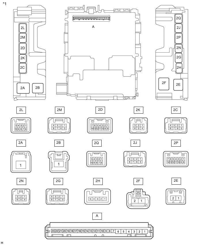
*1 Instrument Panel Junction Block Assembly - - 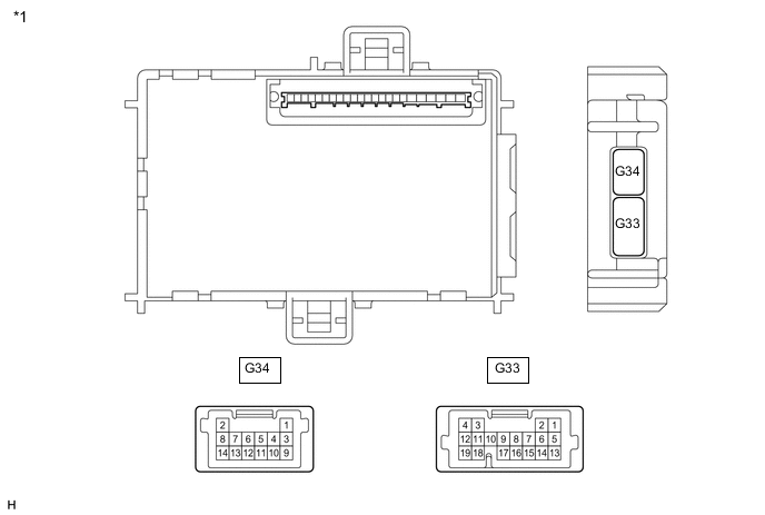
*1 Body ECU - -
-
Remove the body ECU from the instrument panel junction block assembly.
-
Measure the voltage and resistance according to the value(s) in the table below.
Terminal No. (Symbol) Wiring Color Terminal Description Condition Specified Condition A-1 (GND) - Body ground - Ground Always Below 1 Ω A-6 (BECU) - Body ground - Battery power supply Always 11 to 14 V A-7 (IG) - Body ground - Ignition power supply Ignition switch ON 11 to 14 V Ignition switch off Below 1 V -
Install the body ECU to the instrument panel junction block assembly.
-
Measure the voltage and check for pulses according to the value(s) in the table below.
Terminal No. (Symbol) Wiring Color Terminal Description Condition Specified Condition 2N-2 (ACT+) - Body ground LA-B - Body ground Door lock motor lock drive output (all doors) Door control switch (power window regulator master switch assembly) or driver door key cylinder off Below 1 V Door control switch (power window regulator master switch assembly) or driver door key cylinder locked 11 to 14 V 2N-3 (ACT-) - Body ground LA-W - Body ground Door lock motor unlock drive output (all doors) Door control switch (power window regulator master switch assembly) or driver door key cylinder off Below 1 V Door control switch (power window regulator master switch assembly) or driver door key cylinder unlocked 11 to 14 V 2Q-1 (DCTY) - Body ground B - Body ground Driver door courtesy light switch input Driver door open Below 1 V Driver door closed Pulse generation 2Q-2 (ACTY) - Body ground Y - Body ground All door courtesy light switches input except driver door Except driver door open Below 1 V Except driver door closed Pulse generation 2L-4 (DCTY) - Body ground R - Body ground Driver door courtesy light switch input Driver door open Below 1 V Driver door closed Pulse generation G33-2 (LSWP) - Body ground Y - Body ground Except driver door unlock detection switch input Except driver door unlocked Below 1 V Except driver door locked Pulse generation G33-6 (HAZ) - Body ground SB - Body ground Hazard warning signal output Answer-back off 11 to 14 V Answer-back on Below 1 V G33-8 (KSW) - Body ground G - Body ground Unlock warning switch input No key in ignition key cylinder Pulse generation Key in ignition key cylinder Below 1 V G33-9 (PRG) - Body ground V - Body ground Signal output to door control receiver Key inserted into ignition key cylinder → Key pulled out of ignition key cylinder 11 to 14 V → Pulse generation → 11 to 14 V G33-14 (PCTY) - Body ground LG - Body ground Front passenger door courtesy light switch input Front passenger door open Below 1 V Front passenger door closed Pulse generation G33-15 (LSWD) - Body ground R - Body ground Driver door unlock detection switch input Driver door unlocked Below 1 V Driver door locked Pulse generation G33-16 (RDA) - Body ground W - Body ground Signal input from door control receiver Ignition switch off, all doors closed and door control transmitter switch not pressed 11 to 14 V Ignition switch off, all doors closed and door control transmitter switch pressed Pulse generation
-
-
CHECK COMBINATION METER ASSEMBLY