WIRELESS DOOR LOCK CONTROL SYSTEM(w/ Smart Entry and Start System) No Answer-Back
DESCRIPTION
In some cases, wireless door lock control functions are normal but the hazard warning light and wireless door lock buzzer answer-back function* does not operate. In such cases, hazard warning light and wireless door lock buzzer* signal outputs from the body ECU may be malfunctioning.
-
*: w/ Wireless Door Lock Buzzer Answer-back Function
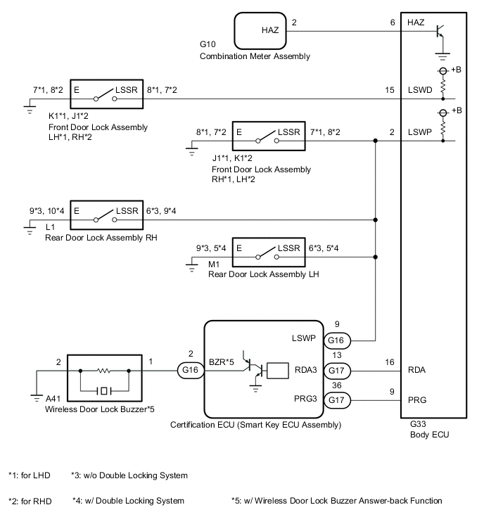
WIRING DIAGRAM
CAUTION / NOTICE / HINT
Note
-
When replacing the certification ECU (smart key ECU assembly), refer to the Service Bulletin.
-
The wireless door lock buzzer answer-back function can be customized. Make sure that this function is ON before performing this.*1
-
Before performing the inspection, check that DTC B27B0 (Smart Entry and Start System) is not output.
-
If the body ECU has been replaced, it is necessary to initialize the body ECU.*2
-
As the door control battery is installed between the vehicle battery and body ECU, first perform the inspections to confirm that there are no malfunctions in the power source circuit for the body ECU before performing this troubleshooting procedure.*3
-
*1: w/ Wireless Door Lock Buzzer Answer-back Function
-
*2: w/ Automatic Light Control System
-
*3: w/ Door Control Battery
PROCEDURE
-
CHECK WIRELESS DOOR LOCK CONTROL FUNCTIONS
-
Check the wireless door lock control function using the electrical key transmitter sub-assembly.
Result Result Proceed to Wireless door lock/unlock operates properly A Wireless door lock/unlock does not operate properly B
B 
GO TO SMART ENTRY AND START SYSTEM (FOR ENTRY FUNCTION) Click here
A 
-
-
INSPECT DOOR LOCK ASSEMBLY (DETECTION UNLOCK SWITCH)
-
for Front Side:
-
Remove the front door lock assembly.
-
Inspect the front door lock assembly.
-
-
for Rear Side:
-
Remove the rear door lock assembly.
-
Inspect the rear door lock assembly.
Result Result Proceed to OK A NG (for Front Side) B NG (for Rear Side) C -
B
REPLACE FRONT DOOR LOCK ASSEMBLY Click here
C
REPLACE REAR DOOR LOCK ASSEMBLY Click here
A
-
-
CHECK HARNESS AND CONNECTOR (DOOR LOCK ASSEMBLY - BODY ECU, CERTIFICATION ECU [SMART KEY ECU ASSEMBLY] AND BODY GROUND)
-
for Driver Side:
-
Disconnect the K1*1 or J1*2 front door lock assembly LH*1 or RH*2 connector.
-
*1: for LHD
-
*2: for RHD
-
-
Disconnect the G33 body ECU connector.
-
Measure the resistance according to the value(s) in the table below.
Standard Resistance for LHD Tester Connection Condition Specified Condition K1-8 (LSSR) - G33-15 (LSWD) Always Below 1 Ω K1-7 (E) - Body ground Always Below 1 Ω K1-8 (LSSR) or G33-15 (LSWD) - Body ground Always 10 kΩ or higher for RHD Tester Connection Condition Specified Condition J1-7 (LSSR) - G33-15 (LSWD) Always Below 1 Ω J1-8 (E) - Body ground Always Below 1 Ω J1-7 (LSSR) or G33-15 (LSWD) - Body ground Always 10 kΩ or higher
-
-
except Driver Side:
-
Disconnect the J1 or K1*2 front door lock assembly RH*1 or LH*2 connector.
-
*1: for LHD
-
*2: for RHD
-
-
Disconnect the L1 rear door lock assembly RH connector.
-
Disconnect the M1 rear door lock assembly LH connector.
-
Disconnect the G33 body ECU connector.
-
Disconnect the G16 certification ECU (smart key ECU assembly) connector.
-
Measure the resistance according to the value(s) in the table below.
Standard Resistance for LHD Tester Connection Condition Specified Condition J1-7 (LSSR) - G33-2 (LSWP) Always Below 1 Ω J1-7 (LSSR) - G16-9 (LSWP) Always Below 1 Ω J1-8 (E) - Body ground Always Below 1 Ω J1-7 (LSSR) or G33-2 (LSWP) - Body ground Always 10 kΩ or higher J1-7 (LSSR) or G16-9 (LSWP) - Body ground Always 10 kΩ or higher L1-6 (LSSR) - G33-2 (LSWP) Always Below 1 Ω L1-6 (LSSR) - G16-9 (LSWP) Always Below 1 Ω L1-9 (E) - Body ground Always Below 1 Ω L1-6 (LSSR) - G33-2 (LSWP) - Body ground Always 10 kΩ or higher L1-6 (LSSR) - G16-9 (LSWP) - Body ground Always 10 kΩ or higher M1-6 (LSSR) - G33-2 (LSWP) Always Below 1 Ω M1-6 (LSSR) - G16-9 (LSWP) Always Below 1 Ω M1-9 (E) - Body ground Always Below 1 Ω M1-6 (LSSR) - G33-2 (LSWP) - Body ground Always 10 kΩ or higher M1-6 (LSSR) - G16-9 (LSWP) - Body ground Always 10 kΩ or higher for RHD, w/o Double Locking System Tester Connection Condition Specified Condition K1-8 (LSSR) - G33-2 (LSWP) Always Below 1 Ω K1-8 (LSSR) - G16-9 (LSWP) Always Below 1 Ω K1-7 (E) - Body ground Always Below 1 Ω K1-8 (LSSR) or G33-2 (LSWP) - Body ground Always 10 kΩ or higher K1-8 (LSSR) or G16-9 (LSWP) - Body ground Always 10 kΩ or higher L1-6 (LSSR) - G33-2 (LSWP) Always Below 1 Ω L1-6 (LSSR) - G16-9 (LSWP) Always Below 1 Ω L1-9 (E) - Body ground Always Below 1 Ω L1-6 (LSSR) - G33-2 (LSWP) - Body ground Always 10 kΩ or higher L1-6 (LSSR) - G16-9 (LSWP) - Body ground Always 10 kΩ or higher M1-6 (LSSR) - G33-2 (LSWP) Always Below 1 Ω M1-6 (LSSR) - G16-9 (LSWP) Always Below 1 Ω M1-9 (E) - Body ground Always Below 1 Ω M1-6 (LSSR) - G33-2 (LSWP) - Body ground Always 10 kΩ or higher M1-6 (LSSR) - G16-9 (LSWP) - Body ground Always 10 kΩ or higher for RHD, w/ Double Locking System Tester Connection Condition Specified Condition K1-8 (LSSR) - G33-2 (LSWP) Always Below 1 Ω K1-8 (LSSR) - G16-9 (LSWP) Always Below 1 Ω K1-7 (E) - Body ground Always Below 1 Ω K1-8 (LSSR) or G33-2 (LSWP) - Body ground Always 10 kΩ or higher K1-8 (LSSR) or G16-9 (LSWP) - Body ground Always 10 kΩ or higher L1-9 (LSSR) - G33-2 (LSWP) Always Below 1 Ω L1-9 (LSSR) - G16-9 (LSWP) Always Below 1 Ω L1-10 (E) - Body ground Always Below 1 Ω L1-9 (LSSR) - G33-2 (LSWP) - Body ground Always 10 kΩ or higher L1-9 (LSSR) - G16-9 (LSWP) - Body ground Always 10 kΩ or higher M1-5 (LSSR) - G33-2 (LSWP) Always Below 1 Ω M1-5 (LSSR) - G16-9 (LSWP) Always Below 1 Ω M1-6 (E) - Body ground Always Below 1 Ω M1-5 (LSSR) - G33-2 (LSWP) - Body ground Always 10 kΩ or higher M1-5 (LSSR) - G16-9 (LSWP) - Body ground Always 10 kΩ or higher
Result Proceed to OK NG -
NG
REPAIR OR REPLACE HARNESS OR CONNECTOR
OK
-
-
CHECK WIRELESS ANSWER-BACK OPERATION
-
Check the wireless answer-back operation using the electrical key transmitter sub-assembly.
Result Result Proceed to Only wireless door lock buzzer answer-back does not occur (w/ Wireless Door Lock Buzzer Answer-back Function) A Only hazard warning light answer-back does not occur B
B 
CHECK HAZARD WARNING LIGHTS OPERATION Click here
A
-
-
PERFORM ACTIVE TEST USING GTS (WIRELESS BUZZER)
-
Connect the GTS to the DLC3.
-
Turn the engine switch on (IG).
-
Turn the GTS on.
-
Enter the following menus: Body Electrical / Entry&Start / Active Test.
-
Perform the Active Test according to the display on the GTS.
Body Electrical > Entry&Start > Active TestTester Display Measurement Item Control Range Diagnostic Note Wireless Buzzer Operation Wireless door lock buzzer OFF/ON -
Body Electrical > Entry&Start > Active TestTester Display Wireless Buzzer Operation Result Result Proceed to Wireless door lock buzzer does not turn on/off A Wireless door lock buzzer turns on/off B
B
REPLACE BODY ECU for LHD: Click here
REPLACE BODY ECU for RHD: Click hereA
-
-
CHECK HARNESS AND CONNECTOR (WIRELESS DOOR LOCK BUZZER - CERTIFICATION ECU [SMART KEY ECU ASSEMBLY] AND BODY GROUND)
-
Disconnect the A41 wireless door lock buzzer connector.
-
Disconnect the G16 certification ECU (smart key ECU assembly) connector.
-
Measure the resistance according to the value(s) in the table below.
Standard Resistance Tester Connection Condition Specified Condition A41-1 - G16-2 (BZR) Always Below 1 Ω A41-2 - Body ground Always Below 1 Ω A41-1 or G16-2 (BZR) - Body ground Always 10 kΩ or higher Result Proceed to OK NG
NG
REPAIR OR REPLACE HARNESS OR CONNECTOR
OK
-
-
REPLACE WIRELESS DOOR LOCK BUZZER
-
Replace the wireless door lock buzzer with a new or known good one.
Result Proceed to NEXT
NEXT
-
-
PERFORM ACTIVE TEST USING GTS (WIRELESS BUZZER)
-
Connect the GTS to the DLC3.
-
Turn the engine switch on (IG).
-
Turn the GTS on.
-
Enter the following menus: Body Electrical / Entry&Start / Active Test.
-
Perform the Active Test according to the display on the GTS.
Body Electrical > Entry&Start > Active TestTester Display Measurement Item Control Range Diagnostic Note Wireless Buzzer Operation Wireless door lock buzzer OFF/ON -
Body Electrical > Entry&Start > Active TestTester Display Wireless Buzzer Operation Result Result Proceed to Wireless door lock buzzer does not turn on/off A Wireless door lock buzzer turns on/off B
A
REPLACE CERTIFICATION ECU (SMART KEY ECU ASSEMBLY)
B
END (WIRELESS DOOR LOCK BUZZER WAS DEFECTIVE)
-
-
CHECK HAZARD WARNING LIGHTS OPERATION
-
Check that the hazard warning lights blink when the hazard warning signal switch is pressed.
OK Hazard warning lights blink. Result Proceed to OK NG
NG
GO TO LIGHTING SYSTEM (PROCEED TO HAZARD WARNING SWITCH CIRCUIT) Click here
OK
-
-
CHECK HARNESS AND CONNECTOR (COMBINATION METER ASSEMBLY - BODY ECU)
-
Disconnect the G10 combination meter assembly connector.
-
Disconnect the G33 body ECU connector.
-
Measure the resistance according to the value(s) in the table below.
Standard Resistance Tester Connection Condition Specified Condition G10-2 (HAZ) - G33-6 (HAZ) Always Below 1 Ω G10-2 (HAZ) or G33-6 (HAZ) - Body ground Always 10 kΩ or higher Result Proceed to OK NG
OK
REPLACE BODY ECU for LHD: Click here
REPLACE BODY ECU for RHD: Click hereNG
REPAIR OR REPLACE HARNESS OR CONNECTOR
-