POWER DOOR LOCK CONTROL SYSTEM Only Back Door cannot be Opened
DESCRIPTION
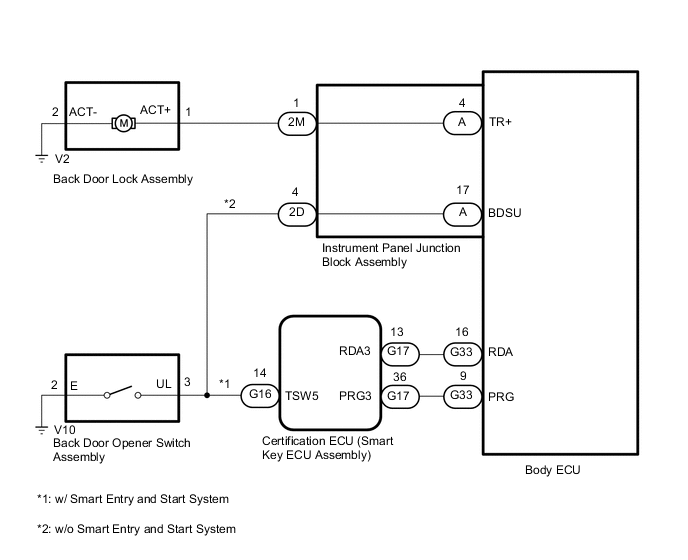
The body ECU receives signals from the certification ECU (smart key ECU assembly). Then, the body ECU activates the back door lock motor.
WIRING DIAGRAM
CAUTION / NOTICE / HINT
Note
-
Inspect the fuses for circuits related to this system before performing the following procedure.
-
If the body ECU has been replaced, it is necessary to initialize the body ECU.
-
Before performing the inspection, check that DTC B27B0 (Smart Entry and Start System) (for Entry Function) is not output.*
-
*: w/ Smart Entry and Start System
PROCEDURE
-
SYSTEM CHECK
-
Check the vehicle specification.
Result Proceed to w/o Smart Entry and Start System w/ Smart Entry and Start System
w/ Smart Entry and Start System 
CHECK SMART ENTRY AND START SYSTEM (for Entry Function) Click here
w/o Smart Entry and Start System 
-
-
INSPECT BACK DOOR OPENER SWITCH ASSEMBLY
-
Remove the back door opener switch assembly.
-
Inspect the back door opener switch assembly.
Result Proceed to OK NG
NG 
REPLACE BACK DOOR OPENER SWITCH ASSEMBLY
OK
-
-
CHECK HARNESS AND CONNECTOR (BACK DOOR OPENER SWITCH ASSEMBLY - INSTRUMENT PANEL JUNCTION BLOCK ASSEMBLY AND BODY GROUND)
-
Disconnect the V2 back door lock assembly connector.
-
Disconnect the 2M instrument panel junction block assembly connector.
-
Measure the resistance according to the value(s) in the table below.
Standard Resistance Tester Connection Condition Specified Condition V10-3 (UL) - 2D-4 Always Below 1 Ω V10-3 (UL) or 2D-4 - Body ground Always 10 kΩ or higher V10-2 (E) - Body ground Always Below 1 Ω Result Proceed to OK NG
NG
REPAIR OR REPLACE HARNESS OR CONNECTOR
OK
-
-
INSPECT INSTRUMENT PANEL JUNCTION BLOCK ASSEMBLY
-
Remove the instrument panel junction block assembly.
-
Remove the body ECU from the instrument panel junction block assembly.
-
Measure the resistance according to the value(s) in the table below.
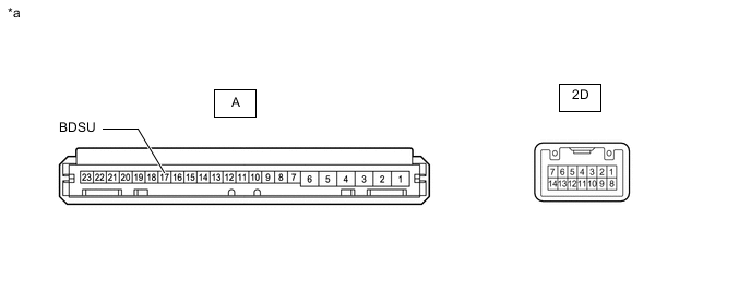
*a Component without harness connected
(Instrument Panel Junction Block Assembly)
- - Standard Resistance Tester Connection Condition Specified Condition A-17 (BDSU) - 2D-4 Always Below 1 Ω Result Proceed to OK NG
OK
GO TO STEP 7 Click here
NG
REPLACE INSTRUMENT PANEL JUNCTION BLOCK ASSEMBLY Click here
-
-
CHECK SMART ENTRY AND START SYSTEM (for Entry Function)
-
Check the smart entry and start system (for Entry Function).
OK Smart entry and start system (for Entry Function) operates normally. Result Proceed to OK NG
NG
GO TO SMART ENTRY AND START SYSTEM (for Entry Function) Click here
OK
-
-
INSPECT BACK DOOR LOCK ASSEMBLY
-
Remove the back door lock assembly.
-
Inspect the back door lock assembly.
Result Proceed to OK NG
NG
REPLACE BACK DOOR LOCK ASSEMBLY Click here
OK
-
-
CHECK HARNESS AND CONNECTOR (BACK DOOR LOCK ASSEMBLY - INSTRUMENT PANEL JUNCTION BLOCK ASSEMBLY AND BODY GROUND)
-
Disconnect the V2 back door lock assembly connector.
-
Disconnect the 2M instrument panel junction block assembly connector.
-
Measure the resistance according to the value(s) in the table below.
Standard Resistance Tester Connection Condition Specified Condition V2-1 (ACT+) - 2M-1 Always Below 1 Ω V2-1 (ACT+) or 2M-1 - Body ground Always 10 kΩ or higher V2-2 (ACT-) - Body ground Always Below 1 Ω Result Proceed to OK NG
NG
REPAIR OR REPLACE HARNESS OR CONNECTOR
OK
-
-
INSPECT INSTRUMENT PANEL JUNCTION BLOCK ASSEMBLY
-
Remove the instrument panel junction block assembly.
-
Remove the body ECU from the instrument panel junction block assembly.
-
Measure the resistance according to the value(s) in the table below.
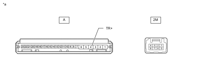
*a Component without harness connected
(Instrument Panel Junction Block Assembly)
- - Standard Resistance Tester Connection Condition Specified Condition A-4 (TR+) - 2M-1 Always Below 1 Ω Result Proceed to OK NG
OK
REPLACE BODY ECU Click here
NG
REPLACE INSTRUMENT PANEL JUNCTION BLOCK ASSEMBLY Click here
-