POWER DOOR LOCK CONTROL SYSTEM TERMINALS OF ECU
-
CHECK INSTRUMENT PANEL JUNCTION BLOCK ASSEMBLY AND BODY ECU
-
Remove the body ECU from the instrument panel junction block assembly.
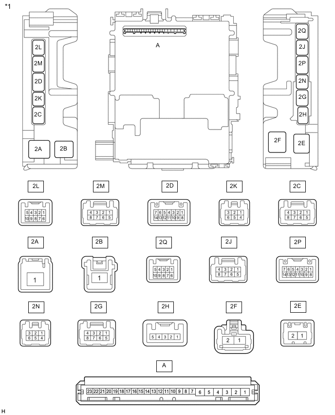
*1 Instrument Panel Junction Block Assembly - - 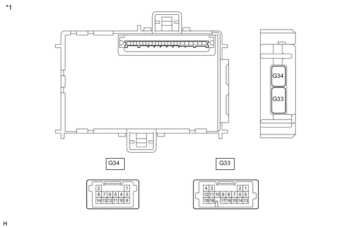
*1 Body ECU - - -
Measure the voltage and resistance according to the value(s) in the table below.
Tech Tips
Measure the values on the wire harness side with the connectors disconnected.
Terminal No. (Symbol) Wiring Color Terminal Description Condition Specified Condition A-1 (GND) - Body ground - Ground Always Below 1 Ω A-6 (BECU) - Body ground - Battery power supply Always 11 to 14 V A-7 (IG) - Body ground - Ignition power supply Ignition switch ON 11 to 14 V Ignition switch off Below 1 V -
Install the body ECU to the instrument panel junction block assembly.
-
Measure the voltage and check for pulses according to the value(s) in the table below.
Terminal No. (Symbol) Wiring Color Terminal Description Condition Specified Condition 2D-4 (BDSU) - Body ground*1 V - Body ground Back door opener switch input Back door opener switch assembly (open switch) off → on Pulse generation 2N-2 (ACT+) - Body ground LA-B - Body ground Door lock motor lock drive output Door control switch (power window regulator master switch assembly) or driver door key cylinder off Below 1 V Door control switch (power window regulator master switch assembly) or driver door key cylinder locked 11 to 14 V 2N-3 (ACT-) - Body ground LA-W - Body ground Door lock motor unlock drive output Door control switch (power window regulator master switch assembly) or driver door key cylinder off Below 1 V Door control switch (power window regulator master switch assembly) or driver door key cylinder unlocked 11 to 14 V 2M-1 (TR+) - Body ground*1 LA-R - Body ground Back door lock motor unlock drive output Back door closed Below 1 V Back door open 11 to 14 V 2L-4 (DCTY) - Body ground R - Body ground Driver door courtesy light switch input Driver door open Below 1 V Driver door closed Pulse generation 2Q-1 (DCTY) - Body ground B - Body ground Driver door courtesy light switch input Driver door open Below 1 V Driver door closed Pulse generation 2Q-2 (ACTY) - Body ground Y - Body ground All door courtesy light switches input except driver door Except driver door open Below 1 V Except driver door closed Pulse generation G33-14 (PCTY) - Body ground LG - Body ground Front passenger door courtesy light switch input Front passenger door open Below 1 V Front passenger door closed Pulse generation G33-19 (L1) - Body ground*2 LG - Body ground Door control switch input Door control switch locked Below 1 V Door control switch off Pulse generation G33-12 (UL1) - Body ground*2 L - Body ground Door control switch input Door control switch unlocked Below 1 V Door control switch off Pulse generation G33-18 (L2) - Body ground GR - Body ground Driver door key-linked lock input Driver door key cylinder turned to lock position Below 1 V Driver door key cylinder off Pulse generation G33-11 (UL2) - Body ground BE - Body ground Driver door key-linked unlock input Driver door key cylinder turned to unlock position Below 1 V Driver door key cylinder off Pulse generation G33-15 (LSWD) - Body ground R - Body ground Driver door unlock detection switch input Driver door unlocked Below 1 V Driver door locked Pulse generation G33-2 (LSWP) - Body ground Y - Body ground Except driver door unlock detection switch input Except driver door unlocked Below 1 V Except driver door locked Pulse generation G33-8 (KSW) - Body ground*2 G - Body ground Unlock warning switch input No key in ignition key cylinder Pulse generation Key in ignition key cylinder Below 1 V
-
*1: w/o Power Back Door System
-
*2: w/o Smart Entry and Start System
-
-
-
CHECK COMBINATION METER ASSEMBLY