CAN COMMUNICATION SYSTEM(for LHD) Short to GND in CAN Bus Line
DESCRIPTION
There may be a short circuit between the CAN bus lines and GND when the resistance between terminals 6 (CANH) and 4 (CG) or terminals 14 (CANL) and 4 (CG) of the DLC3 is below 200 Ω.
| Symptom | Trouble Area |
|---|---|
| The resistance between terminals 6 (CANH) and 4 (CG) or terminals 14 (CANL) and 4 (CG) of the DLC3 is below 200 Ω. |
|
*2: w/ Smart Entry and Start System
*3: w/ Navigation System
*4: w/ Audio and Visual System
*5: for LED Headlight
*6: for 4WD
*7: w/ VSC
WIRING DIAGRAM
CAUTION / NOTICE / HINT
Note
-
Because the order of diagnosis is important to allow correct diagnosis, make sure to begin troubleshooting using How to Proceed with Troubleshooting when CAN communication system related DTCs are output.
-
Before measuring the resistance of the CAN bus, turn the ignition switch off and leave the vehicle for 1 minute or more without operating the key, switches or opening or closing the doors. After that, disconnect the cable from the negative (-) battery terminal and leave the vehicle for 1 minute or more before measuring the resistance.
-
After turning the ignition switch off, waiting time may be required before disconnecting the cable from the battery terminal. Therefore, make sure to read the disconnecting the cable from the battery terminal notice before proceeding with work.
Click here
-
The vehicle is equipped with an SRS (Supplemental Restraint System) which includes components such as airbags. Before servicing (including removal or installation of parts), be sure to read the Precaution in the SRS.
for Type A:
for Type B:
-
When replacing the combination meter assembly, make sure to replace it with a new one.
-
Before replacing the certification ECU (smart key ECU assembly), refer to the service bulletin.
Tech Tips
-
Operating the ignition switch, any switches or any doors triggers related ECU and sensor communication with the CAN, which causes resistance variation.
-
Even after DTCs are cleared, if a DTC is stored again after driving the vehicle for a while, the malfunction may be occurring due to vibration of the vehicle. In such a case, wiggling the ECUs or wire harness while performing the inspection below may help determine the cause of the malfunction.
-
Connectors that connect to the CAN junction connector can be distinguished by the color of their CAN bus lines. When the connectors have been disconnected from the CAN junction connector, reconnecting the connectors to non-original positions on the CAN junction connector does not affect system performance. However, it is preferred to reconnect the connectors to their original positions to avoid negative effects on the wiring such as tension on the wiring harnesses, and to make future maintenance easier.
PROCEDURE
-
CHECK FOR SHORT TO GND IN CAN BUS WIRE (DLC3 CAN BRANCH WIRE)
-
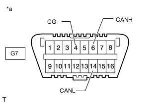
*a Front view of DLC3 Disconnect the cable from the negative (-) battery terminal.
-
Disconnect the No. 1 CAN junction connector.
-
Measure the resistance according to the value(s) in the table below.
Standard Resistance Tester Connection Condition Specified Condition G7-6 (CANH) - G7-4 (CG) Cable disconnected from negative (-) battery terminal 200 Ω or higher G7-14 (CANL) - G7-4 (CG) Cable disconnected from negative (-) battery terminal 200 Ω or higher Result Proceed to OK NG
NG 
REPAIR OR REPLACE CAN BRANCH WIRE CONNECTED TO DLC3 (CANH, CANL)
OK 
-
-
CONNECT CONNECTOR
-
Reconnect the No. 1 CAN junction connector.
Result Proceed to NEXT
NEXT
-
-
CHECK FOR SHORT TO GND IN CAN BUS WIRE (NO. 2 CAN JUNCTION CONNECTOR SIDE)
-
*a Front view of DLC3 Disconnect the No. 2 CAN junction connector.
-
Measure the resistance according to the value(s) in the table below.
Standard Resistance Tester Connection Condition Specified Condition G7-6 (CANH) - G7-4 (CG) Cable disconnected from negative (-) battery terminal 200 Ω or higher G7-14 (CANL) - G7-4 (CG) Cable disconnected from negative (-) battery terminal 200 Ω or higher Result Proceed to OK NG
NG 
CONNECT CONNECTOR Click here
OK
-
-
CHECK FOR SHORT TO GND IN CAN BUS WIRE (NO. 2 CAN JUNCTION CONNECTOR)
-
Disconnect the No. 2 CAN junction connectors.
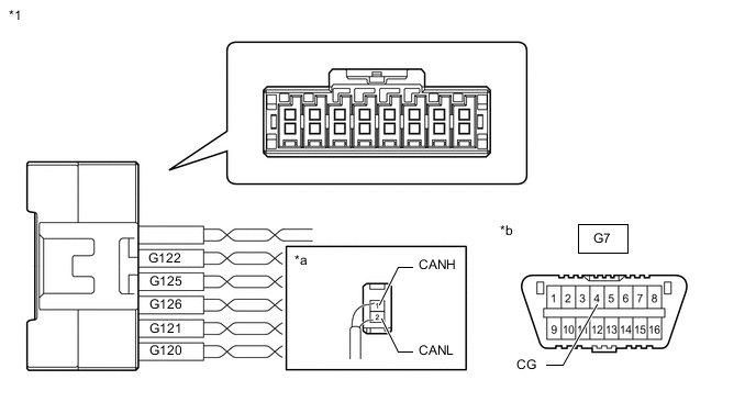
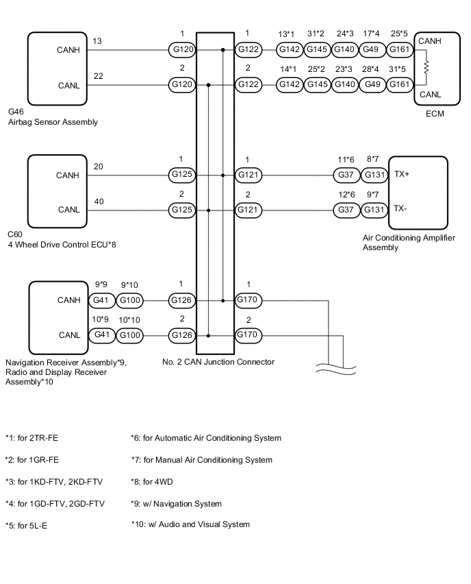
*1 No. 2 CAN Junction Connector - - *a Rear view of wire harness connector
(to No. 2 CAN Junction Connector)
*b Front view of DLC3 -
Measure the resistance according to the value(s) in the table below.
Wiring Color Code Color (CANH Side) Color (CANL Side) Connect to G120 Y W Airbag Sensor Assembly G121 GR W Air Conditioning Amplifier Assembly G122 B W ECM G125 R W 4 Wheel Drive Control ECU*1 G126 V W
-
Navigation Receiver Assembly*2
-
Radio and Display Receiver Assembly*3
*1: for 4WD
*2: w/ Navigation System
*3: w/ Audio and Visual System
Standard Resistance *1: for 4WDTester Connection Condition Specified Condition G120-1 (CANH) - G7-4 (CG) Cable disconnected from negative (-) battery terminal 200 Ω or higher G120-2 (CANL) - G7-4 (CG) G121-1 (CANH) - G7-4 (CG) Cable disconnected from negative (-) battery terminal 200 Ω or higher G121-2 (CANL) - G7-4 (CG) G122-1 (CANH) - G7-4 (CG) Cable disconnected from negative (-) battery terminal 200 Ω or higher G122-2 (CANL) - G7-4 (CG) G125-1 (CANH) - G7-4 (CG)*1 Cable disconnected from negative (-) battery terminal 200 Ω or higher G125-2 (CANL) - G7-4 (CG)*1 G126-1 (CANH) - G7-4 (CG)*2, *3 Cable disconnected from negative (-) battery terminal 200 Ω or higher G126-2 (CANL) - G7-4 (CG)*2, *3
*2: w/ Navigation System
*3: w/ Audio and Visual System
Result Result Proceed to OK A NG (to airbag sensor assembly CAN branch wire) B NG (to air conditioning amplifier assembly CAN branch wire) (for Automatic Air Conditioning System) C NG (to air conditioning amplifier assembly CAN branch wire) (for Manual Air Conditioning System) D NG (to ECM CAN main wire) E NG (to 4 wheel drive control ECU CAN branch wire) (for 4WD) F NG (to navigation receiver assembly CAN branch wire) (w/ Navigation System) G NG (to radio and display receiver assembly CAN branch wire) (w/ Audio and Visual System) H -
A
REPLACE NO. 2 CAN JUNCTION CONNECTOR
C
CONNECT CONNECTOR Click here
D
CONNECT CONNECTOR Click here
E
CONNECT CONNECTOR Click here
F
CONNECT CONNECTOR Click here
G
CONNECT CONNECTOR Click here
H
CONNECT CONNECTOR Click here
B
-
-
CONNECT CONNECTOR
-
Reconnect the No. 2 CAN junction connector.
Result Proceed to NEXT
NEXT
-
-
CHECK FOR SHORT TO GND IN CAN BUS WIRE (AIRBAG SENSOR ASSEMBLY BRANCH WIRE)
-
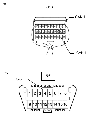
*a Rear view of wire harness connector
(to Airbag Sensor Assembly)
*b Front view of DLC3 Disconnect the airbag sensor assembly connector.
for Type A:
for Type B:
-
Measure the resistance according to the value(s) in the table below.
Standard Resistance Tester Connection Condition Specified Condition G46-13 (CANH) - G7-4 (CG) Cable disconnected from negative (-) battery terminal 200 Ω or higher G46-22 (CANL) - G7-4 (CG) Cable disconnected from negative (-) battery terminal 200 Ω or higher Result Proceed to OK NG
OK
REPLACE AIRBAG SENSOR ASSEMBLY Click here
NG
REPAIR OR REPLACE CAN BRANCH WIRE CONNECTED TO AIRBAG SENSOR ASSEMBLY (CANH, CANL)
-
-
CONNECT CONNECTOR
-
Reconnect the No. 2 CAN junction connector.
Result Proceed to NEXT
NEXT
-
-
CHECK FOR SHORT TO GND IN CAN BUS WIRE (AIR CONDITIONING AMPLIFIER ASSEMBLY BRANCH WIRE)
-
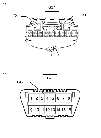
*a Rear view of wire harness connector
(to Air Conditioning Amplifier Assembly)
*b Front view of DLC3 Disconnect the air conditioning amplifier assembly connector.
-
Measure the resistance according to the value(s) in the table below.
Standard Resistance Tester Connection Condition Specified Condition G37-11 (TX+) - G7-4 (CG) Cable disconnected from negative (-) battery terminal 200 Ω or higher G37-12 (TX-) - G7-4 (CG) Cable disconnected from negative (-) battery terminal 200 Ω or higher Result Proceed to OK NG
OK
REPLACE AIR CONDITIONING AMPLIFIER ASSEMBLY Click here
NG
REPAIR OR REPLACE CAN BRANCH WIRE CONNECTED TO AIR CONDITIONING AMPLIFIER ASSEMBLY (TX+, TX-)
-
-
CONNECT CONNECTOR
-
Reconnect the No. 2 CAN junction connector.
Result Proceed to NEXT
NEXT
-
-
CHECK FOR SHORT TO GND IN CAN BUS WIRE (AIR CONDITIONING AMPLIFIER ASSEMBLY BRANCH WIRE)
-
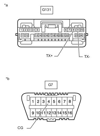
*a Front view of wire harness connector
(to Air Conditioning Amplifier Assembly)
*b Front view of DLC3 Disconnect the air conditioning amplifier assembly connector.
-
Measure the resistance according to the value(s) in the table below.
Standard Resistance Tester Connection Condition Specified Condition G131-8 (TX+) - G7-4 (CG) Cable disconnected from negative (-) battery terminal 200 Ω or higher G131-9 (TX-) - G7-4 (CG) Cable disconnected from negative (-) battery terminal 200 Ω or higher Result Proceed to OK NG
OK
REPLACE AIR CONDITIONING AMPLIFIER ASSEMBLY Click here
NG
REPAIR OR REPLACE CAN BRANCH WIRE CONNECTED TO AIR CONDITIONING AMPLIFIER ASSEMBLY (TX+, TX-)
-
-
CONNECT CONNECTOR
-
Reconnect the No. 2 CAN junction connector.
Result Proceed to NEXT
NEXT
-
-
CHECK FOR SHORT TO GND IN CAN BUS WIRE (ECM MAIN WIRE)
-
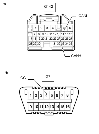
*a Front view of wire harness connector
(to ECM)
*b Front view of DLC3 for 2TR-FE:
-
Disconnect the ECM connector.
-
Measure the resistance according to the value(s) in the table below.
Standard Resistance Tester Connection Condition Specified Condition G142-13 (CANH) - G7-4 (CG) Cable disconnected from negative (-) battery terminal 200 Ω or higher G142-14 (CANL) - G7-4 (CG) Cable disconnected from negative (-) battery terminal 200 Ω or higher
-
-
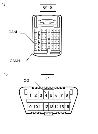
*a Front view of wire harness connector
(to ECM)
*b Front view of DLC3 for 1GR-FE:
-
Disconnect the ECM connector.
-
Measure the resistance according to the value(s) in the table below.
Standard Resistance Tester Connection Condition Specified Condition G145-31 (CANH) - G7-4 (CG) Cable disconnected from negative (-) battery terminal 200 Ω or higher G145-25 (CANL) - G7-4 (CG) Cable disconnected from negative (-) battery terminal 200 Ω or higher
-
-
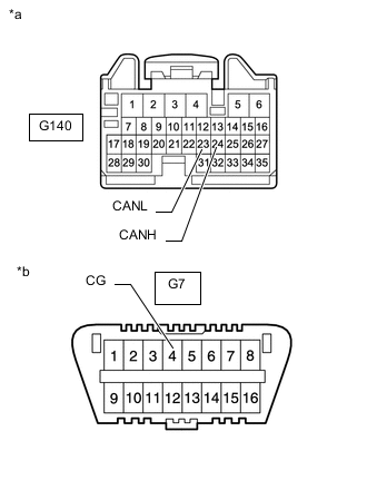
*a Front view of wire harness connector
(to ECM)
*b Front view of DLC3 for 1KD-FTV, 2KD-FTV:
-
Disconnect the ECM connector.
-
Measure the resistance according to the value(s) in the table below.
Standard Resistance Tester Connection Condition Specified Condition G140-24 (CANH) - G7-4 (CG) Cable disconnected from negative (-) battery terminal 200 Ω or higher G140-23 (CANL) - G7-4 (CG) Cable disconnected from negative (-) battery terminal 200 Ω or higher
-
-
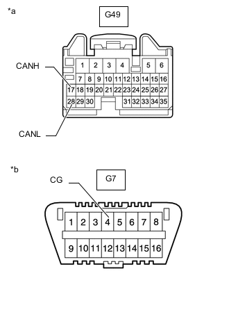
*a Front view of wire harness connector
(to ECM)
*b Front view of DLC3 for 1GD-FTV, 2GD-FTV:
-
Disconnect the ECM connector.
-
Measure the resistance according to the value(s) in the table below.
Standard Resistance Tester Connection Condition Specified Condition G49-17 (CANH) - G7-4 (CG) Cable disconnected from negative (-) battery terminal 200 Ω or higher G49-28 (CANL) - G7-4 (CG) Cable disconnected from negative (-) battery terminal 200 Ω or higher
-
-
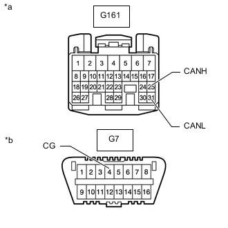
*a Front view of wire harness connector
(to ECM)
*b Front view of DLC3 for 5L-E:
-
Disconnect the ECM connector.
-
Measure the resistance according to the value(s) in the table below.
Standard Resistance Tester Connection Condition Specified Condition G161-25 (CANH) - G7-4 (CG) Cable disconnected from negative (-) battery terminal 200 Ω or higher G161-31 (CANL) - G7-4 (CG) Cable disconnected from negative (-) battery terminal 200 Ω or higher
Result Proceed to OK NG -
OK
REPLACE ECM for 2TR-FE: REPLACE ECM Click here
REPLACE ECM for 1GR-FE: REPLACE ECM Click here
REPLACE ECM for 1KD-FTV: REPLACE ECM Click here
REPLACE ECM for 2KD-FTV: REPLACE ECM Click here
REPLACE ECM for 1GD-FTV: REPLACE ECM Click here
REPLACE ECM for 2GD-FTV: REPLACE ECM Click here
REPLACE ECM for 5L-E: REPLACE ECM Click hereNG
REPAIR OR REPLACE CAN MAIN WIRE CONNECTED TO ECM (CANH, CANL)
-
-
CONNECT CONNECTOR
-
Reconnect the No. 2 CAN junction connector.
Result Proceed to NEXT
NEXT
-
-
CHECK FOR SHORT TO GND IN CAN BUS WIRE (4 WHEEL DRIVE CONTROL ECU BRANCH WIRE)
-
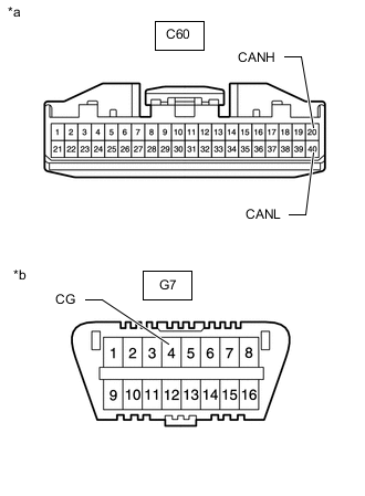
*a Front view of wire harness connector
(to 4 Wheel Drive Control ECU)
*b Front view of DLC3 Disconnect the 4 wheel drive control ECU connector.
-
Measure the resistance according to the value(s) in the table below.
Standard Resistance Tester Connection Condition Specified Condition C60-20 (CANH) - G7-4 (CG) Cable disconnected from negative (-) battery terminal 200 Ω or higher C60-40 (CANL) - G7-4 (CG) Cable disconnected from negative (-) battery terminal 200 Ω or higher Result Proceed to OK NG
OK
REPLACE 4 WHEEL DRIVE CONTROL ECU Click here
NG
REPAIR OR REPLACE CAN BRANCH WIRE CONNECTED TO 4 WHEEL DRIVE CONTROL ECU (CANH, CANL)
-
-
CONNECT CONNECTOR
-
Reconnect the No. 2 CAN junction connector.
Result Proceed to NEXT
NEXT
-
-
CHECK FOR SHORT TO GND IN CAN BUS WIRE (NAVIGATION RECEIVER ASSEMBLY BRANCH WIRE)
-
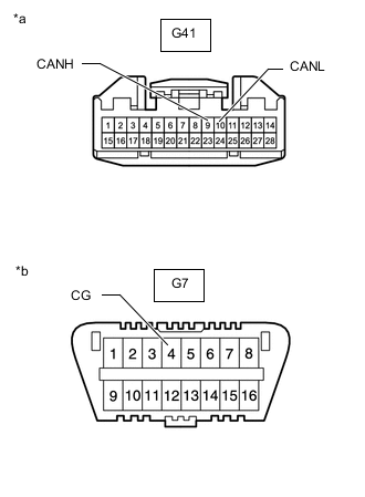
*a Front view of wire harness connector
(to Navigation Receiver Assembly)
*b Front view of DLC3 Disconnect the navigation receiver assembly connector.
-
Measure the resistance according to the value(s) in the table below.
Standard Resistance Tester Connection Condition Specified Condition G41-9 (CANH) - G7-4 (CG) Cable disconnected from negative (-) battery terminal 200 Ω or higher G41-10 (CANL) - G7-4 (CG) Cable disconnected from negative (-) battery terminal 200 Ω or higher Result Proceed to OK NG
OK
REPLACE NAVIGATION RECEIVER ASSEMBLY Click here
NG
REPAIR OR REPLACE CAN BRANCH WIRE CONNECTED TO NAVIGATION RECEIVER ASSEMBLY (CANH, CANL)
-
-
CONNECT CONNECTOR
-
Reconnect the No. 2 CAN junction connector.
Result Proceed to NEXT
NEXT
-
-
CHECK FOR SHORT TO GND IN CAN BUS WIRE (RADIO AND DISPLAY RECEIVER ASSEMBLY BRANCH WIRE)
-
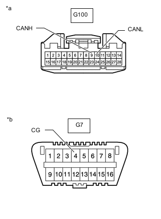
*a Front view of wire harness connector
(to Radio and Display Receiver Assembly)
*b Front view of DLC3 Disconnect the radio and display receiver assembly connector.
-
Measure the resistance according to the value(s) in the table below.
Standard Resistance Tester Connection Condition Specified Condition G100-9 (CANH) - G7-4 (CG) Cable disconnected from negative (-) battery terminal 200 Ω or higher G100-10 (CANL) - G7-4 (CG) Cable disconnected from negative (-) battery terminal 200 Ω or higher Result Proceed to OK NG
OK
REPLACE RADIO AND DISPLAY RECEIVER ASSEMBLY Click here
NG
REPAIR OR REPLACE CAN BRANCH WIRE CONNECTED TO RADIO AND DISPLAY RECEIVER ASSEMBLY (CANH, CANL)
-
-
CONNECT CONNECTOR
-
Reconnect the No. 2 CAN junction connector.
Result Proceed to NEXT
NEXT
-
-
CHECK FOR SHORT TO GND IN CAN BUS WIRE (NO. 1 CAN JUNCTION CONNECTOR)
-
Disconnect the No. 1 CAN junction connector.
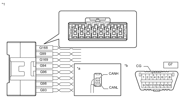
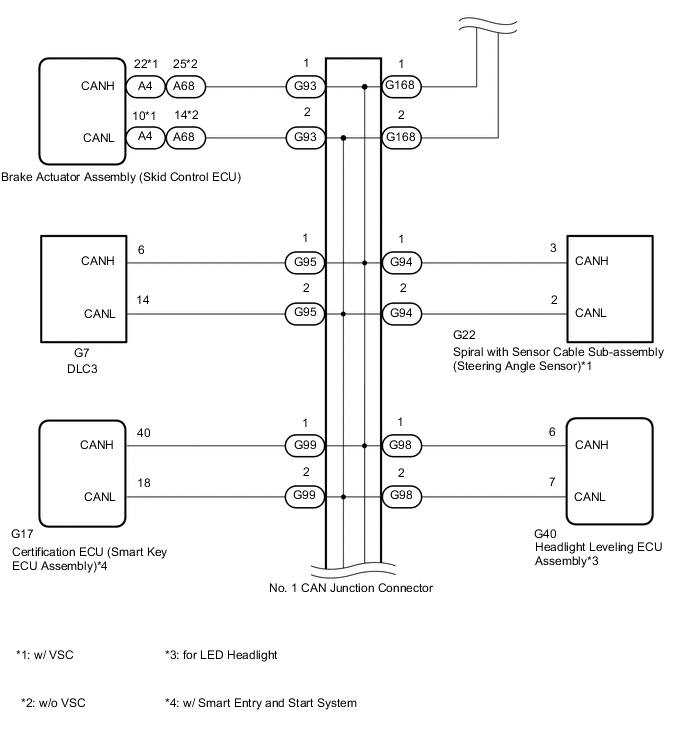
*1 No. 1 CAN Junction Connector - - *a Rear view of wire harness connector
(to No. 1 CAN Junction Connector)
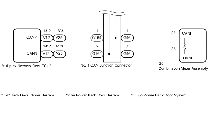
*b Front view of DLC3 Wiring Color Code Color (CANH Side) Color (CANL Side) Connect to G93 B W Brake Actuator Assembly (Skid Control ECU) G94 BE W Spiral with Sensor Cable Sub-assembly (Steering Angle Sensor)*4 G96 P W Combination Meter Assembly G98 V W Headlight Leveling ECU Assembly*1 G99 G W Certification ECU (Smart Key ECU Assembly)*2 G168 LG W No. 2 CAN Junction Connector G169 SB W Multiplex Network Door ECU*3 *1: for LED Headlight
*2: w/ Smart Entry and Start System
*3: w/ Back Door Closer System
*4: w/ VSC
-
Measure the resistance according to the value(s) in the table below.
Standard Resistance *1: for LED HeadlightTester Connection Condition Specified Condition G93-1 (CANH) - G7-4 (CG) Cable disconnected from negative (-) battery terminal 200 Ω or higher G93-2 (CANL) - G7-4 (CG) G94-1 (CANH) - G7-4 (CG)*4 Cable disconnected from negative (-) battery terminal 200 Ω or higher G94-2 (CANL) - G7-4 (CG)*4 G96-1 (CANH) - G7-4 (CG) Cable disconnected from negative (-) battery terminal 200 Ω or higher G96-2 (CANL) - G7-4 (CG) G98-1 (CANH) - G7-4 (CG)*1 Cable disconnected from negative (-) battery terminal 200 Ω or higher G98-2 (CANL) - G7-4 (CG)*1 G99-1 (CANH) - G7-4 (CG)*2 Cable disconnected from negative (-) battery terminal 200 Ω or higher G99-2 (CANL) - G7-4 (CG)*2 G168-1 (CANH) - G7-4 (CG) Cable disconnected from negative (-) battery terminal 200 Ω or higher G168-2 (CANL) - G7-4 (CG) G169-1 (CANH) - G7-4 (CG)*3 Cable disconnected from negative (-) battery terminal 200 Ω or higher G169-2 (CANL) - G7-4 (CG)*3
*2: w/ Smart Entry and Start System
*3: w/ Back Door Closer System
*4: w/ VSC
Result Result Proceed to OK A NG (to brake actuator assembly [skid control ECU] CAN branch wire) B NG (to spiral with sensor cable sub-assembly [steering angle sensor] CAN branch wire) (w/ VSC) C NG (to combination meter assembly CAN main wire) D NG (to headlight leveling ECU assembly CAN branch wire) (for LED Headlight) E NG (to certification ECU [smart key ECU assembly] CAN branch wire) (w/ Smart Entry and Start System) F NG (to multiplex network door ECU CAN branch wire) (w/ Back Door Closer System) G NG (to No. 2 CAN junction connector CAN main wire) H
A
REPLACE NO. 1 CAN JUNCTION CONNECTOR
C
CONNECT CONNECTOR Click here
D
CONNECT CONNECTOR Click here
E
CONNECT CONNECTOR Click here
F
CONNECT CONNECTOR Click here
G
CONNECT CONNECTOR Click here
H
REPAIR OR REPLACE CAN MAIN WIRE OR CONNECTOR (NO. 1 CAN JUNCTION CONNECTOR - NO. 2 CAN JUNCTION CONNECTOR)
B
-
-
CONNECT CONNECTOR
-
Reconnect the No. 1 CAN junction connector.
Result Proceed to NEXT
NEXT
-
-
CHECK FOR SHORT TO GND IN CAN BUS WIRE (SKID CONTROL ECU BRANCH WIRE)
-
Disconnect the brake actuator assembly (skid control ECU) connector.
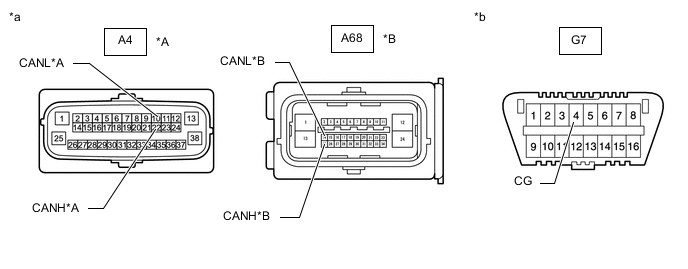
*A w/ VSC *B w/o VSC *a Front view of wire harness connector
(to Brake Actuator Assembly [Skid Control ECU])
*b Front view of DLC3 -
Measure the resistance according to the value(s) in the table below.
Standard Resistance w/ VSC Tester Connection Condition Specified Condition A4-22 (CANH) - G7-4 (CG) Cable disconnected from negative (-) battery terminal 200 Ω or higher A4-10 (CANL) - G7-4 (CG) Cable disconnected from negative (-) battery terminal 200 Ω or higher w/o VSC Tester Connection Condition Specified Condition A68-25 (CANH) - G7-4 (CG) Cable disconnected from negative (-) battery terminal 200 Ω or higher A68-14 (CANL) - G7-4 (CG) Cable disconnected from negative (-) battery terminal 200 Ω or higher Result Proceed to OK NG
OK
REPLACE BRAKE ACTUATOR ASSEMBLY (SKID CONTROL ECU) w/ VSC: REPLACE BRAKE ACTUATOR ASSEMBLY (SKID CONTROL ECU) Click here
REPLACE BRAKE ACTUATOR ASSEMBLY (SKID CONTROL ECU) w/o VSC: REPLACE BRAKE ACTUATOR ASSEMBLY (SKID CONTROL ECU) Click hereNG
REPAIR OR REPLACE CAN BRANCH WIRE CONNECTED TO SKID CONTROL ECU (CANH, CANL)
-
-
CONNECT CONNECTOR
-
Reconnect the No. 1 CAN junction connector.
Result Proceed to NEXT
NEXT
-
-
CHECK FOR SHORT TO GND IN CAN BUS WIRE (STEERING ANGLE SENSOR BRANCH WIRE)
-
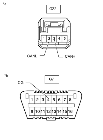
*a Front view of wire harness connector
(to Spiral with Sensor Cable Sub-assembly [Steering Angle Sensor])
*b Front view of DLC3 Disconnect the spiral with sensor cable sub-assembly (steering angle sensor) connector.
-
Measure the resistance according to the value(s) in the table below.
Standard Resistance Tester Connection Condition Specified Condition G22-3 (CANH) - G7-4 (CG) Cable disconnected from negative (-) battery terminal 200 Ω or higher G22-2 (CANL) - G7-4 (CG) Cable disconnected from negative (-) battery terminal 200 Ω or higher Result Proceed to OK NG
OK
REPLACE SPIRAL WITH SENSOR CABLE SUB-ASSEMBLY (STEERING ANGLE SENSOR) Click here
NG
REPAIR OR REPLACE CAN BRANCH WIRE CONNECTED TO SPIRAL WITH SENSOR CABLE SUB-ASSEMBLY (CANH, CANL)
-
-
CONNECT CONNECTOR
-
Reconnect the No. 1 CAN junction connector.
Result Proceed to NEXT
NEXT
-
-
CHECK FOR SHORT TO GND IN CAN BUS WIRE (COMBINATION METER ASSEMBLY MAIN WIRE)
-
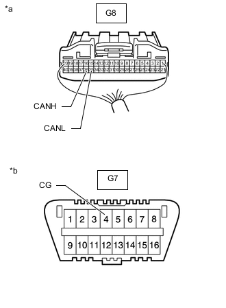
*a Rear view of wire harness connector
(to Combination Meter Assembly)
*b Front view of DLC3 Disconnect the combination meter assembly connector.
-
Measure the resistance according to the value(s) in the table below.
Standard Resistance Tester Connection Condition Specified Condition G8-36 (CANH) - G7-4 (CG) Cable disconnected from negative (-) battery terminal 200 Ω or higher G8-35 (CANL) - G7-4 (CG) Cable disconnected from negative (-) battery terminal 200 Ω or higher Result Proceed to OK NG
OK
REPLACE COMBINATION METER ASSEMBLY Click here
NG
REPAIR OR REPLACE CAN MAIN WIRE CONNECTED TO COMBINATION METER ASSEMBLY (CANH, CANL)
-
-
CONNECT CONNECTOR
-
Reconnect the No. 1 CAN junction connector.
Result Proceed to NEXT
NEXT
-
-
CHECK FOR SHORT TO GND IN CAN BUS WIRE (HEADLIGHT LEVELING ECU ASSEMBLY BRANCH WIRE)
-
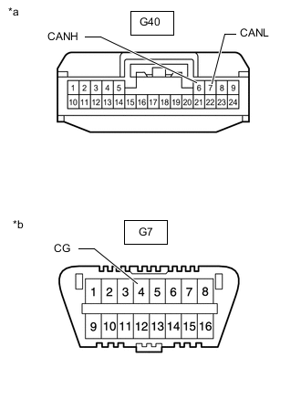
*a Front view of wire harness connector
(to Headlight Leveling ECU Assembly)
*b Front view of DLC3 Disconnect the headlight leveling ECU assembly connector.
-
Measure the resistance according to the value(s) in the table below.
Standard Resistance Tester Connection Condition Specified Condition G40-6 (CANH) - G7-4 (CG) Cable disconnected from negative (-) battery terminal 200 Ω or higher G40-7 (CANL) - G7-4 (CG) Cable disconnected from negative (-) battery terminal 200 Ω or higher Result Proceed to OK NG
OK
REPLACE HEADLIGHT LEVELING ECU ASSEMBLY Click here
NG
REPAIR OR REPLACE CAN BRANCH WIRE CONNECTED TO HEADLIGHT LEVELING ECU ASSEMBLY (CANH, CANL)
-
-
CONNECT CONNECTOR
-
Reconnect the No. 1 CAN junction connector.
Result Proceed to NEXT
NEXT
-
-
CHECK FOR SHORT TO GND IN CAN BUS WIRE (CERTIFICATION ECU CAN BRANCH WIRE)
-
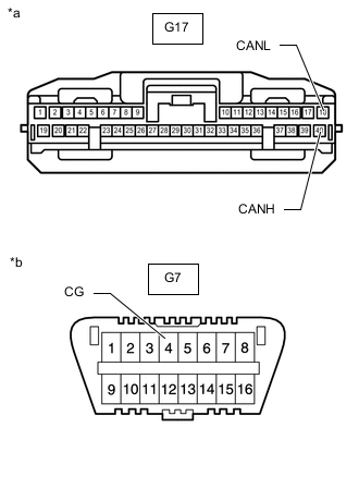
*a Front view of wire harness connector
(to Certification ECU [Smart Key ECU Assembly])
*b Front view of DLC3 Disconnect the certification ECU (smart key ECU assembly) connector.
-
Measure the resistance according to the value(s) in the table below.
Standard Resistance Tester Connection Condition Specified Condition G17-40 (CANH) - G7-4 (CG) Cable disconnected from negative (-) battery terminal 200 Ω or higher G17-18 (CANL) - G7-4 (CG) Cable disconnected from negative (-) battery terminal 200 Ω or higher Result Proceed to OK NG
OK
REPLACE CERTIFICATION ECU (SMART KEY ECU ASSEMBLY)
NG
REPAIR OR REPLACE CAN BRANCH WIRE CONNECTED TO CERTIFICATION ECU (CANH, CANL)
-
-
CONNECT CONNECTOR
-
Reconnect the No. 1 CAN junction connector.
Result Proceed to NEXT
NEXT
-
-
CHECK FOR SHORT TO GND IN CAN BUS WIRE (MULTIPLEX NETWORK DOOR ECU BRANCH WIRE)
-
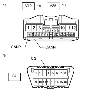
*A w/ Power Back Door System *B w/o Power Back Door System *a Front view of wire harness connector
(to Multiplex Network Door ECU)
*b Front view of DLC3 Disconnect the multiplex network door ECU connector.
-
Measure the resistance according to the value(s) in the table below.
Standard Resistance w/ Power Back Door System: Tester Connection Condition Specified Condition V12-13 (CANP) - G7-4 (CG) Cable disconnected from negative (-) battery terminal 200 Ω or higher V12-14 (CANN) - G7-4 (CG) Cable disconnected from negative (-) battery terminal 200 Ω or higher w/o Power Back Door System: Tester Connection Condition Specified Condition V25-13 (CANP) - G7-4 (CG) Cable disconnected from negative (-) battery terminal 200 Ω or higher V25-14 (CANN) - G7-4 (CG) Cable disconnected from negative (-) battery terminal 200 Ω or higher Result Proceed to OK NG
OK
REPLACE MULTIPLEX NETWORK DOOR ECU Click here
NG
REPAIR OR REPLACE CAN BRANCH WIRE CONNECTED TO MULTIPLEX NETWORK DOOR ECU (CANP, CANN)
-