CAN COMMUNICATION SYSTEM(for LHD) ECM Communication Stop Mode
DESCRIPTION
| Detection Item | Symptom | Trouble Area |
|---|---|---|
| ECM Communication Stop Mode | Either condition is met:
|
|
WIRING DIAGRAM
Figure 1. for 2TR-FE:
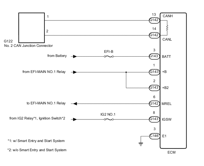
Figure 2. for 1GR-FE:

Figure 3. for 1KD-FTV, 2KD-FTV:
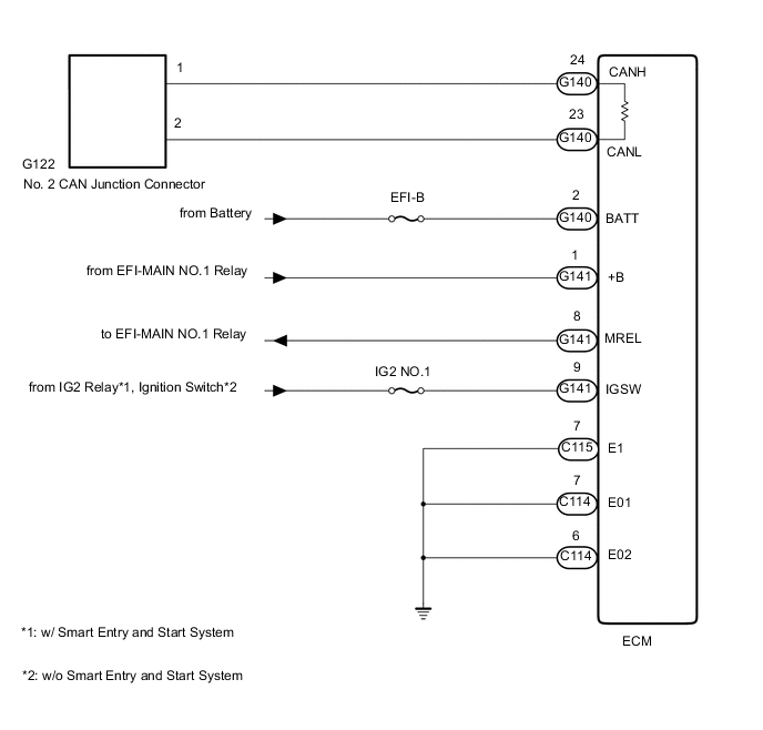
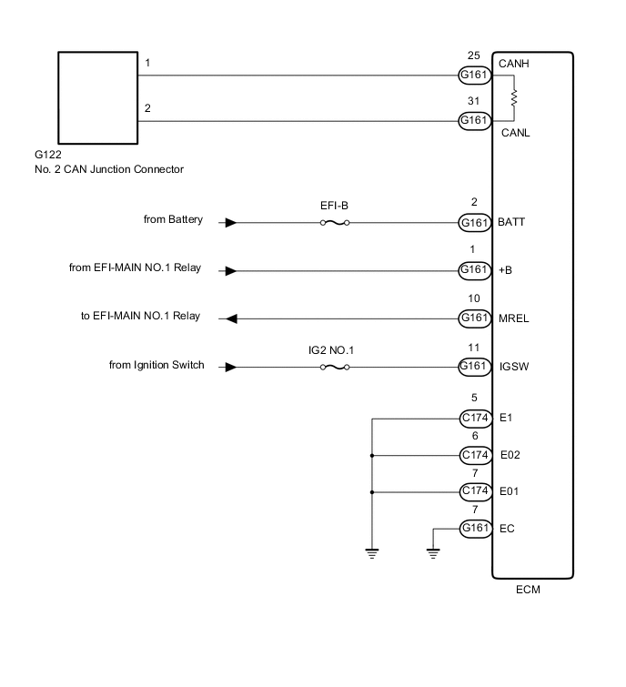
Figure 4. for 1GD-FTV, 2GD-FTV:
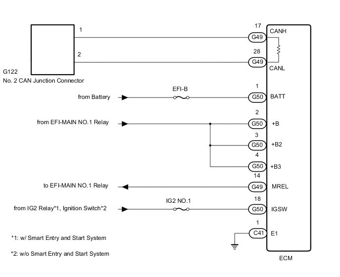
Figure 5. for 5L-E:
CAUTION / NOTICE / HINT
Note
-
Because the order of diagnosis is important to allow correct diagnosis, make sure to begin troubleshooting using How to Proceed with Troubleshooting when CAN communication system related DTCs are output.
-
Before measuring the resistance of the CAN bus, turn the ignition switch off and leave the vehicle for 1 minute or more without operating the key, switches or opening or closing the doors. After that, disconnect the cable from the negative (-) battery terminal and leave the vehicle for 1 minute or more before measuring the resistance.
-
After turning the ignition switch off, waiting time may be required before disconnecting the cable from the battery terminal. Therefore, make sure to read the disconnecting the cable from the battery terminal notice before proceeding with work.
-
Inspect the fuses for circuits related to this system before performing the following procedure.
-
DTC check procedure: Turn the ignition switch ON, wait at least 20 seconds, and then drive the vehicle at a speed of 15 km/h (9 mph) or more for 3 seconds or more.
-
After the repair, perform CAN Bus Check and check that all the ECUs and sensors connected to the CAN communication system are displayed.
Tech Tips
-
Operating the ignition switch, any switches or any doors triggers related ECU and sensor communication with the CAN, which causes resistance variation.
-
Even after DTCs are cleared, if a DTC is stored again after driving the vehicle for a while, the malfunction may be occurring due to vibration of the vehicle. In such a case, wiggling the ECUs or wire harness while performing the inspection below may help determine the cause of the malfunction.
PROCEDURE
-
CHECK VEHICLE TYPE
-
Check vehicle type.
Result Result Proceed to for 2TR-FE A for 1GR-FE B for 1KD-FTV, 2KD-FTV C for 1GD-FTV, 2GD-FTV D for 5L-E E
B 
CHECK FOR OPEN IN CAN BUS WIRE (ECM CAN MAIN WIRE) Click here
C
CHECK FOR OPEN IN CAN BUS WIRE (ECM CAN MAIN WIRE) Click here
D
CHECK FOR OPEN IN CAN BUS WIRE (ECM CAN MAIN WIRE) Click here
E
CHECK FOR OPEN IN CAN BUS WIRE (ECM CAN MAIN WIRE) Click here
A 
-
-
CHECK FOR OPEN IN CAN BUS WIRE (ECM CAN MAIN WIRE)
-
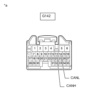
*a Front view of wire harness connector
(to ECM)
Disconnect the cable from the negative (-) battery terminal.
-
Disconnect the ECM connector.
-
Measure the resistance according to the value(s) in the table below.
Standard Resistance Tester Connection Condition Specified Condition G142-13 (CANH) - G142-14 (CANL) Cable disconnected from negative (-) battery terminal 108 to 132 Ω Result Proceed to OK NG
NG 
REPAIR OR REPLACE ECM CAN MAIN WIRE OR CONNECTOR (CANH, CANL)
OK
-
-
CHECK HARNESS AND CONNECTOR (ECM - BATTERY AND BODY GROUND)
-
Connect the cable to the negative (-) battery terminal.
Note
When disconnecting the cable, some systems need to be initialized after the cable is reconnected.
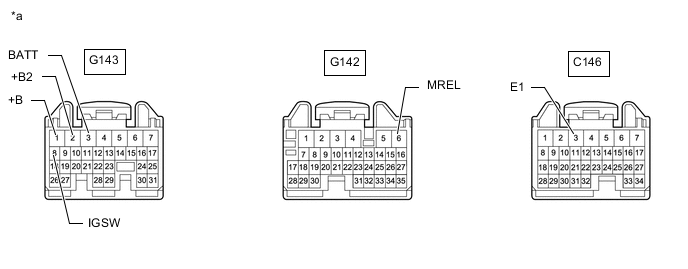
*a Front view of wire harness connector
(to ECM)
- - -
Disconnect the ECM connectors.
-
Measure the voltage according to the value(s) in the table below.
Standard Voltage Tester Connection Condition Specified Condition G143-3 (BATT) - Body ground Always 11 to 14 V G143-1 (+B) - Body ground Battery positive (+) voltage applied to terminal G142-6 (MREL) 11 to 14 V G143-2 (+B2) - Body ground Battery positive (+) voltage applied to terminal G142-6 (MREL) 11 to 14 V G143-8 (IGSW) - Body ground Ignition switch ON 11 to 14 V -
Measure the resistance according to the value(s) in the table below.
Standard Resistance Tester Connection Condition Specified Condition C146-3 (E1) - Body ground Always Below 1 Ω Result Proceed to OK NG
OK
REPLACE ECM Click here
NG
REPAIR OR REPLACE HARNESS OR CONNECTOR
-
-
CHECK FOR OPEN IN CAN BUS WIRE (ECM CAN MAIN WIRE)
-
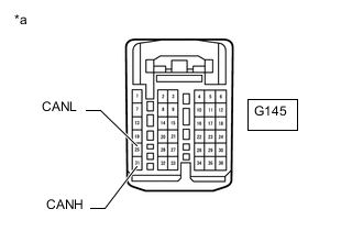
*a Front view of wire harness connector
(to ECM)
Disconnect the cable from the negative (-) battery terminal.
-
Disconnect the ECM connector.
-
Measure the resistance according to the value(s) in the table below.
Standard Resistance Tester Connection Connector Specified Condition G145-31 (CANH) - G145-25 (CANL) Cable disconnected from negative (-) battery terminal 108 to 132 Ω Result Proceed to OK NG
NG
REPAIR OR REPLACE ECM CAN MAIN WIRE OR CONNECTOR (CANH, CANL)
OK
-
-
CHECK HARNESS AND CONNECTOR (ECM - BATTERY AND BODY GROUND)
-
Connect the cable to the negative (-) battery terminal.
Note
When disconnecting the cable, some systems need to be initialized after the cable is reconnected.
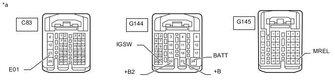
*a Front view of wire harness connector
(to ECM)
- - -
Disconnect the ECM connectors.
-
Measure the voltage according to the value(s) in the table below.
Standard Voltage Tester Connection Condition Specified Condition G144-24 (BATT) - Body ground Always 11 to 14 V G144-23 (+B) - Body ground Battery positive (+) voltage applied to terminal G145-36 (MREL) 11 to 14 V G144-22 (+B2) - Body ground Battery positive (+) voltage applied to terminal G145-36 (MREL) 11 to 14 V G144-21 (IGSW) - Body ground Ignition switch ON 11 to 14 V -
Measure the resistance according to the value(s) in the table below.
Standard Resistance Tester Connection Condition Specified Condition C83-23 (E01) - Body ground Always Below 1 Ω Result Proceed to OK NG
OK
REPLACE ECM Click here
NG
REPAIR OR REPLACE HARNESS OR CONNECTOR
-
-
CHECK FOR OPEN IN CAN BUS WIRE (ECM CAN MAIN WIRE)
-
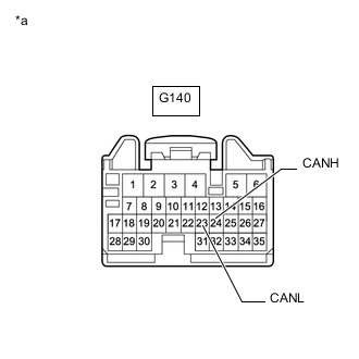
*a Front view of wire harness connector
(to ECM)
Disconnect the cable from the negative (-) battery terminal.
-
Disconnect the ECM connector.
-
Measure the resistance according to the value(s) in the table below.
Standard Resistance Tester Connection Condition Specified Condition G140-24 (CANH) - G140-23 (CANL) Cable disconnected from negative (-) battery terminal 108 to 132 Ω Result Proceed to OK NG
NG
REPAIR OR REPLACE ECM CAN MAIN WIRE OR CONNECTOR (CANH, CANL)
OK
-
-
CHECK HARNESS AND CONNECTOR (ECM - BATTERY AND BODY GROUND)
-
Connect the cable to the negative (-) battery terminal.
Note
When disconnecting the cable, some systems need to be initialized after the cable is reconnected.
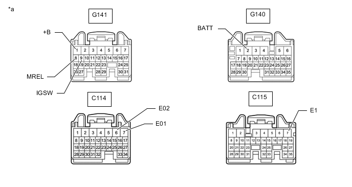
*a Front view of wire harness connector
(to ECM)
- - -
Disconnect the ECM connectors.
-
Measure the voltage according to the value(s) in the table below.
Standard Voltage Tester Connection Condition Specified Condition G140-2 (BATT) - Body ground Always 11 to 14 V G141-1 (+B) - Body ground Battery positive (+) voltage applied to terminal G141-8 (MREL) 11 to 14 V G141-9 (IGSW) - Body ground Ignition switch ON 11 to 14 V -
Measure the resistance according to the value(s) in the table below.
Standard Resistance Tester Connection Condition Specified Condition C115-7 (E1) - Body ground Always Below 1 Ω C114-7 (E01) - Body ground Always Below 1 Ω C114-6 (E02) - Body ground Always Below 1 Ω Result Proceed to OK NG
OK
REPLACE ECM for 1KD-FTV: REPLACE ECM Click here
REPLACE ECM for 2KD-FTV: REPLACE ECM Click hereNG
REPAIR OR REPLACE HARNESS OR CONNECTOR
-
-
CHECK FOR OPEN IN CAN BUS WIRE (ECM CAN MAIN WIRE)
-
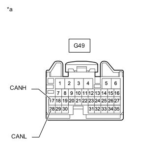
*a Front view of wire harness connector
(to ECM)
Disconnect the cable from the negative (-) battery terminal.
-
Disconnect the ECM connector.
-
Measure the resistance according to the value(s) in the table below.
Standard Resistance Tester Connection Condition Specified Condition G49-17 (CANH) - G49-28 (CANL) Cable disconnected from negative (-) battery terminal 108 to 132 Ω Result Proceed to OK NG
NG
REPAIR OR REPLACE ECM CAN MAIN WIRE OR CONNECTOR (CANH, CANL)
OK
-
-
CHECK HARNESS AND CONNECTOR (ECM - BATTERY AND BODY GROUND)
-
Connect the cable to the negative (-) battery terminal.
Note
When disconnecting the cable, some systems need to be initialized after the cable is reconnected.
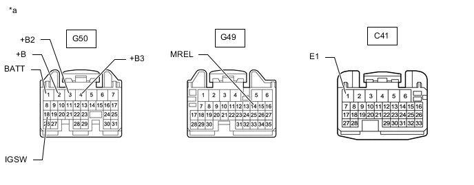
*a Front view of wire harness connector
(to ECM)
- - -
Disconnect the ECM connectors.
-
Measure the voltage according to the value(s) in the table below.
Standard Voltage Tester Connection Condition Specified Condition G50-1 (BATT) - Body ground Always 11 to 14 V G50-2 (+B) - Body ground Battery positive (+) voltage applied to terminal G49-14 (MREL) 11 to 14 V G50-3 (+B2) - Body ground Battery positive (+) voltage applied to terminal G49-14 (MREL) 11 to 14 V G50-4 (+B3) - Body ground Battery positive (+) voltage applied to terminal G49-14 (MREL) 11 to 14 V G50-18 (IGSW) - Body ground Ignition switch ON 11 to 14 V -
Measure the resistance according to the value(s) in the table below.
Standard Resistance Tester Connection Condition Specified Condition C41-1 (E1) - Body ground Always Below 1 Ω Result Proceed to OK NG
OK
REPLACE ECM for 1GD-FTV: REPLACE ECM Click here
REPLACE ECM for 2GD-FTV: REPLACE ECM Click hereNG
REPAIR OR REPLACE HARNESS OR CONNECTOR
-
-
CHECK FOR OPEN IN CAN BUS WIRE (ECM CAN MAIN WIRE)
-
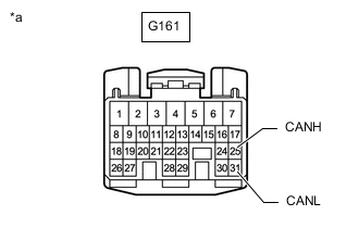
*a Front view of wire harness connector
(to ECM)
Disconnect the cable from the negative (-) battery terminal.
-
Disconnect the ECM connector.
-
Measure the resistance according to the value(s) in the table below.
Standard Resistance Tester Connection Condition Specified Condition G161-25 (CANH) - G161-31 (CANL) Cable disconnected from negative (-) battery terminal 108 to 132 Ω Result Proceed to OK NG
NG
REPAIR OR REPLACE ECM CAN MAIN WIRE OR CONNECTOR (CANH, CANL)
OK
-
-
CHECK HARNESS AND CONNECTOR (ECM - BATTERY AND BODY GROUND)
-
Connect the cable to the negative (-) battery terminal.
Note
When disconnecting the cable, some systems need to be initialized after the cable is reconnected.
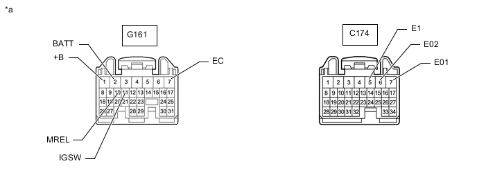
*a Front view of wire harness connector
(to ECM)
- - -
Disconnect the ECM connector.
-
Measure the voltage according to the value(s) in the table below.
Standard Voltage Tester Connection Condition Specified Condition G161-2 (BATT) - Body ground Always 11 to 14 V G161-1 (+B) - Body ground Battery positive (+) voltage applied to terminal G161-10 (MREL) 11 to 14 V G161-11 (IGSW) - Body ground Ignition switch ON 11 to 14 V -
Measure the resistance according to the value(s) in the table below.
Standard Resistance Tester Connection Condition Specified Condition G161-7 (EC) - Body ground Always Below 1 Ω C174-5 (E1) - Body ground Always Below 1 Ω C174-6 (E02) - Body ground Always Below 1 Ω C174-7 (E01) - Body ground Always Below 1 Ω Result Proceed to OK NG
OK
REPLACE ECM Click here
NG
REPAIR OR REPLACE HARNESS OR CONNECTOR
-