CAN COMMUNICATION SYSTEM(for LHD) TERMINALS OF ECU
Tech Tips
Operating the ignition switch, any switches or any doors triggers related ECU and sensor communication with the CAN, which causes resistance variation.
-
DISCONNECT CABLE FROM NEGATIVE BATTERY TERMINAL
-
Disconnect the cable from the negative (-) battery terminal before measuring the resistances of the CAN main wire and the CAN branch wire.
CAUTION:
Wait at least 90 seconds after disconnecting the cable from the negative (-) battery terminal to disable the SRS system.
Note
-
Before measuring the resistance, leave the vehicle for at least 1 minute and do not operate the ignition switch, any switches or any doors. If doors need to be opened in order to check connectors, open the doors and leave them open.
-
After turning the cable disconnected from negative (-) battery terminal, waiting time may be required before disconnecting the cable from the battery terminal. Therefore, make sure to read the disconnecting the cable from the battery terminal notice before proceeding with work.
-
When disconnecting the cable, some systems need to be initialized after the cable is reconnected.
-
-
-
JUNCTION CONNECTOR
-
No. 1 CAN Junction Connector
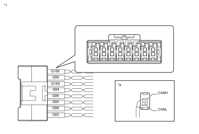
*1 No. 1 CAN Junction Connector - - *a Rear view of wire harness connector
(to No. 1 CAN Junction Connector)
- - No. 1 CAN Junction Connector Wiring Color Connect to G93-1 (CANH) B Brake actuator assembly (skid control ECU) G93-2 (CANL) W G94-1 (CANH) BE Spiral with sensor cable sub-assembly (steering angle sensor)*4 G94-2 (CANL) W G95-1 (CANH) L DLC3 G95-2 (CANL) W G96-1 (CANH) P Combination meter assembly G96-2 (CANL) W G98-1 (CANH) V Headlight leveling ECU assembly*1 G98-2 (CANL) W G99-1 (CANH) G Certification ECU (smart key ECU assembly)*2 G99-2 (CANL) W G168-1 (CANH) LG No. 2 CAN junction connector G168-2 (CANL) W G169-1 (CANH) SB Multiplex network door ECU*3 G169-2 (CANL) W *1: for LED Headlight
*2: w/ Smart Entry and Start System
*3: w/ Back Door Closer System
*4: w/ VSC
-
No. 2 CAN Junction Connector
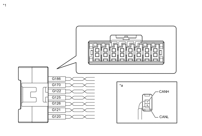
*1 No. 2 CAN Junction Connector - - *a Rear view of wire harness connector
(to No. 2 CAN Junction Connector)
- - No. 2 CAN Junction Connector Wiring Color Connect to G120-1 (CANH) Y Airbag sensor assembly G120-2 (CANL) W G121-1 (CANH) GR Air conditioning amplifier assembly G121-2 (CANL) W G122-1 (CANH) B ECM G122-2 (CANL) W G125-1 (CANH) R 4 wheel drive control ECU*1 G125-2 (CANL) W G126-1 (CANH) V
-
Navigation receiver assembly*2
-
Radio and display receiver assembly*3
G126-2 (CANL) W G170-1 (CANH) LG No. 1 CAN junction connector G170-2 (CANL) W G186-1 (CANH) P Telematics transceiver*4 G186-2 (CANL) W *1: for 4WD
*2: w/ Navigation System
*3: w/ Audio and Visual System
*4: w/ Telematics Transceiver
-
-
-
CHECK DLC3
-
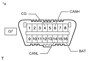
*a Front view of DLC3 Disconnect the cable from the negative (-) battery terminal before measuring the resistances of the CAN main wire and the CAN branch wire.
CAUTION:
Wait at least 90 seconds after disconnecting the cable from the negative (-) battery terminal to disable the SRS system.
Note
-
After turning the cable disconnected from negative (-) battery terminal, waiting time may be required before disconnecting the cable from the battery terminal. Therefore, make sure to read the disconnecting the cable from the battery terminal notice before proceeding with work.
-
When disconnecting the cable, some systems need to be initialized after the cable is reconnected.
Click here
-
-
Measure the resistance according to the value(s) in the table below.
Terminal No. (Symbol) Wiring Color Terminal Description Condition Specified Condition G7-6 (CANH) - G7-14 (CANL) L - W HIGH-level CAN bus wire - LOW-level CAN bus wire Cable disconnected from negative (-) battery terminal 54 to 69 Ω G7-6 (CANH) - G7-4 (CG) L - W-B HIGH-level CAN bus wire - GND Cable disconnected from negative (-) battery terminal 200 Ω or higher G7-14 (CANL) - G7-4 (CG) W - W-B LOW-level CAN bus wire - GND Cable disconnected from negative (-) battery terminal 200 Ω or higher G7-6 (CANH) - G7-16 (BAT) L - G HIGH-level CAN bus wire - Battery positive (+) Cable disconnected from negative (-) battery terminal 6 kΩ or higher G7-14 (CANL) - G7-16 (BAT) W - G LOW-level CAN bus wire - Battery positive (+) Cable disconnected from negative (-) battery terminal 6 kΩ or higher
-
-
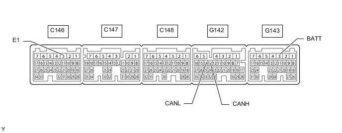
CHECK ECM (for 2TR-FE)
-
Disconnect the ECM connectors.
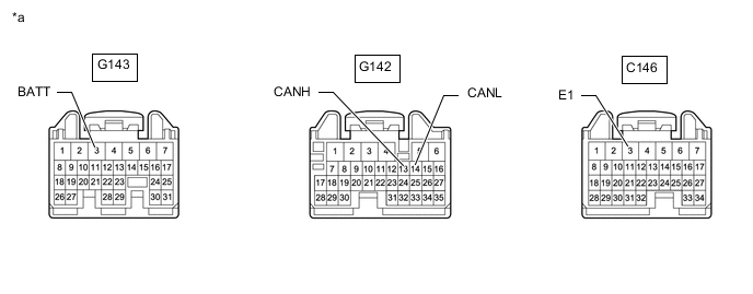
*a Front view of wire harness connector
(to ECM)
- - -
Measure the resistance according to the value(s) in the table below.
Terminal No. (Symbol) Wiring Color Terminal Description Condition Specified Condition G142-13 (CANH) - G142-14 (CANL) B - W HIGH-level CAN bus wire - LOW-level CAN bus wire Cable disconnected from negative (-) battery terminal 108 to 132 Ω G142-13 (CANH) - C146-3 (E1) B - W-B HIGH-level CAN bus wire - GND Cable disconnected from negative (-) battery terminal 200 Ω or higher G142-14 (CANL) - C146-3 (E1) W - W-B LOW-level CAN bus wire - GND Cable disconnected from negative (-) battery terminal 200 Ω or higher G142-13 (CANH) - G143-3 (BATT) B - Y HIGH-level CAN bus wire - Battery positive (+) Cable disconnected from negative (-) battery terminal 6 kΩ or higher G142-14 (CANL) - G143-3 (BATT) W - Y LOW-level CAN bus wire - Battery positive (+) Cable disconnected from negative (-) battery terminal 6 kΩ or higher
-
-
CHECK ECM (for 1GR-FE)
-
Disconnect the ECM connectors.
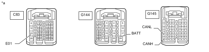
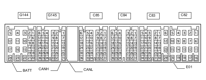
*a Front view of wire harness connector
(to ECM)
- - -
Measure the resistance according to the value(s) in the table below.
Terminal No. (Symbol) Wiring Color Terminal Description Condition Specified Condition G145-31 (CANH) - G145-25 (CANL) B - W HIGH-level CAN bus wire - LOW-level CAN bus wire Cable disconnected from negative (-) battery terminal 108 to 132 Ω G145-31 (CANH) - C83-23 (E01) B - W-B HIGH-level CAN bus wire - GND Cable disconnected from negative (-) battery terminal 200 Ω or higher G145-25 (CANL) - C83-23 (E01) W - W-B LOW-level CAN bus wire - GND Cable disconnected from negative (-) battery terminal 200 Ω or higher G145-31 (CANH) - G144-24 (BATT) B - Y HIGH-level CAN bus wire - Battery positive (+) Cable disconnected from negative (-) battery terminal 6 kΩ or higher G145-25 (CANL) - G144-24 (BATT) W - Y LOW-level CAN bus wire - Battery positive (+) Cable disconnected from negative (-) battery terminal 6 kΩ or higher
-
-
CHECK ECM (for 1GD-FTV, 2GD-FTV)
-
Disconnect the ECM connectors.
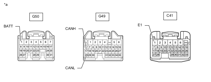
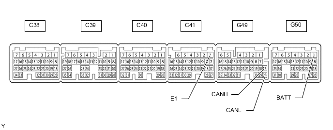
*a Front view of wire harness connector
(to ECM)
- - -
Measure the resistance according to the value(s) in the table below.
Terminal No. (Symbol) Wiring Color Terminal Description Condition Specified Condition G49-17 (CANH) - G49-28 (CANL) B - W HIGH-level CAN bus wire - LOW-level CAN bus wire Cable disconnected from negative (-) battery terminal 108 to 132 Ω G49-17 (CANH) - C41-1 (E1) B - W-B HIGH-level CAN bus wire - GND Cable disconnected from negative (-) battery terminal 200 Ω or higher G49-28 (CANL) - C41-1 (E1) W - W-B LOW-level CAN bus wire - GND Cable disconnected from negative (-) battery terminal 200 Ω or higher G49-17 (CANH) - G50-1 (BATT) B - Y HIGH-level CAN bus wire - Battery positive (+) Cable disconnected from negative (-) battery terminal 6 kΩ or higher G49-28 (CANL) - G50-1 (BATT) W - Y LOW-level CAN bus wire - Battery positive (+) Cable disconnected from negative (-) battery terminal 6 kΩ or higher
-
-
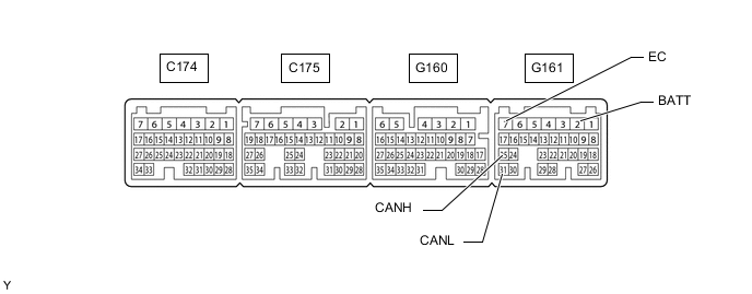
CHECK ECM (for 5L-E)
-
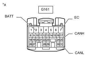
*a Front view of wire harness connector
(to ECM)
Disconnect the ECM connector.
-
Measure the resistance according to the value(s) in the table below.
Terminal No. (Symbol) Wiring Color Terminal Description Condition Specified Condition G161-25 (CANH) - G161-31 (CANL) B - W HIGH-level CAN bus wire - LOW-level CAN bus wire Cable disconnected from negative (-) battery terminal 108 to 132 Ω G161-25 (CANH) - G161-7 (EC) B - BR HIGH-level CAN bus wire - GND Cable disconnected from negative (-) battery terminal 200 Ω or higher G161-31 (CANL) - G161-7 (EC) W - BR LOW-level CAN bus wire - GND Cable disconnected from negative (-) battery terminal 200 Ω or higher G161-25 (CANH) - G161-2 (BATT) B - Y HIGH-level CAN bus wire - Battery positive (+) Cable disconnected from negative (-) battery terminal 6 kΩ or higher G161-31 (CANL) - G161-2 (BATT) W - Y LOW-level CAN bus wire - Battery positive (+) Cable disconnected from negative (-) battery terminal 6 kΩ or higher
-
-
CHECK COMBINATION METER ASSEMBLY

-
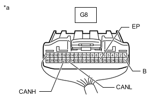
*a Rear view of wire harness connector
(to Combination Meter Assembly)
Disconnect the combination meter assembly connector.
-
Measure the resistance according to the value(s) in the table below.
Terminal No. (Symbol) Wiring Color Terminal Description Condition Specified Condition G8-36 (CANH) - G8-35 (CANL) P - W HIGH-level CAN bus wire - LOW-level CAN bus wire Cable disconnected from negative (-) battery terminal 108 to 132 Ω G8-36 (CANH) - G8-27 (EP) P - W-B HIGH-level CAN bus wire - GND Cable disconnected from negative (-) battery terminal 200 Ω or higher G8-35 (CANL) - G8-27 (EP) W - W-B LOW-level CAN bus wire - GND Cable disconnected from negative (-) battery terminal 200 Ω or higher G8-36 (CANH) - G8-21 (B) P - W HIGH-level CAN bus wire - Battery positive (+) Cable disconnected from negative (-) battery terminal 6 kΩ or higher G8-35 (CANL) - G8-21 (B) W - W LOW-level CAN bus wire - Battery positive (+) Cable disconnected from negative (-) battery terminal 6 kΩ or higher
-
-
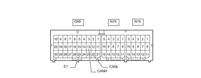
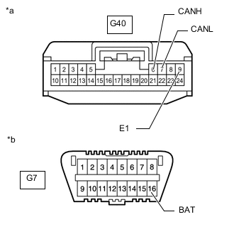
CHECK AIRBAG SENSOR ASSEMBLY
Figure 1. Type A:
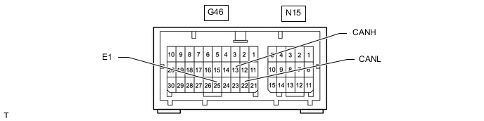
Figure 2. Type B:
-
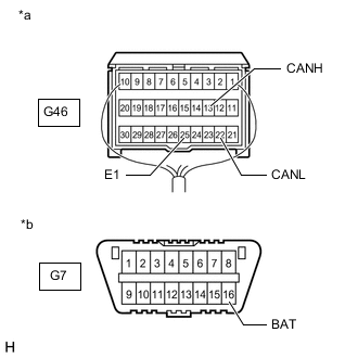
*a Rear view of wire harness connector
(to Airbag Sensor Assembly)
*b Front view of DLC3 Disconnect the airbag sensor assembly connector.
for Type A:
for Type B:
-
Measure the resistance according to the value(s) in the table below.
Terminal No. (Symbol) Wiring Color Terminal Description Condition Specified Condition G46-13 (CANH) - G46-22 (CANL) Y - W HIGH-level CAN bus wire - LOW-level CAN bus wire Cable disconnected from negative (-) battery terminal 54 to 69 Ω G46-13 (CANH) - G46-25 (E1) Y - W-B HIGH-level CAN bus wire - GND Cable disconnected from negative (-) battery terminal 200 Ω or higher G46-22 (CANL) - G46-25 (E1) W - W-B LOW-level CAN bus wire - GND Cable disconnected from negative (-) battery terminal 200 Ω or higher G46-13 (CANH) - G7-16 (BAT) Y - G HIGH-level CAN bus wire - Battery positive (+) Cable disconnected from negative (-) battery terminal 6 kΩ or higher G46-22 (CANL) - G7-16 (BAT) W - G LOW-level CAN bus wire - Battery positive (+) Cable disconnected from negative (-) battery terminal 6 kΩ or higher
-
-
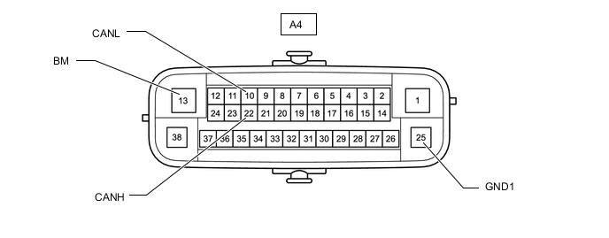
CHECK BRAKE ACTUATOR ASSEMBLY (SKID CONTROL ECU) (w/ VSC)
-
Disconnect the brake actuator assembly (skid control ECU) connector.
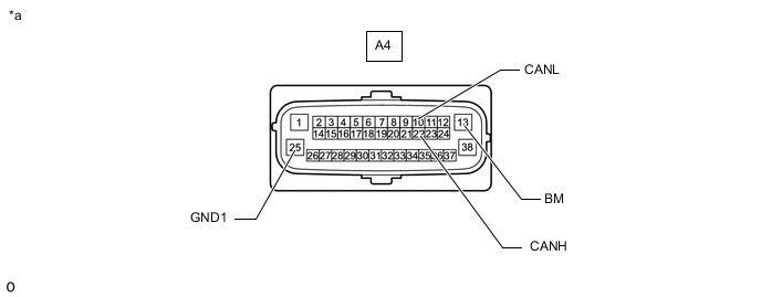
*a Front view of wire harness connector
(to Brake Actuator Assembly [Skid Control ECU])
- - -
Measure the resistance according to the value(s) in the table below.
Terminal No. (Symbol) Wiring Color Terminal Description Condition Specified Condition A4-22 (CANH) - A4-10 (CANL) B - W HIGH-level CAN bus wire - LOW-level CAN bus wire Cable disconnected from negative (-) battery terminal 54 to 69 Ω A4-22 (CANH) - A4-25 (GND1) B - W-B HIGH-level CAN bus wire - GND Cable disconnected from negative (-) battery terminal 200 Ω or higher A4-10 (CANL) - A4-25 (GND1) W - W-B LOW-level CAN bus wire - GND Cable disconnected from negative (-) battery terminal 200 Ω or higher A4-22 (CANH) - A4-13 (BM) B - R HIGH-level CAN bus wire - Battery positive (+) Cable disconnected from negative (-) battery terminal 6 kΩ or higher A4-10 (CANL) - A4-13 (BM) W - R LOW-level CAN bus wire - Battery positive (+) Cable disconnected from negative (-) battery terminal 6 kΩ or higher
-
-
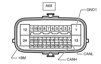
CHECK BRAKE ACTUATOR ASSEMBLY (SKID CONTROL ECU) (w/o VSC)
-
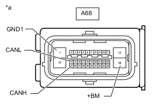
*a Front view of wire harness connector
(to Brake Actuator Assembly [Skid Control ECU])
Disconnect the brake actuator assembly (skid control ECU) connector.
-
Measure the resistance according to the value(s) in the table below.
Terminal No. (Symbol) Wiring Color Terminal Description Condition Specified Condition A68-25 (CANH) - A68-14 (CANL) B - W HIGH-level CAN bus wire - LOW-level CAN bus wire Cable disconnected from negative (-) battery terminal 54 to 69 Ω A68-25 (CANH) - A68-1 (GND1) B - W-B HIGH-level CAN bus wire - GND Cable disconnected from negative (-) battery terminal 200 Ω or higher A68-14 (CANL) - A68-1 (GND1) W - W-B LOW-level CAN bus wire - GND Cable disconnected from negative (-) battery terminal 200 Ω or higher A68-25 (CANH) - A68-24 (+BM) B - R HIGH-level CAN bus wire - Battery positive (+) Cable disconnected from negative (-) battery terminal 6 kΩ or higher A68-14 (CANL) - A68-24 (+BM) W - R LOW-level CAN bus wire - Battery positive (+) Cable disconnected from negative (-) battery terminal 6 kΩ or higher
-
-
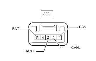
CHECK SPIRAL WITH SENSOR CABLE SUB-ASSEMBLY (STEERING ANGLE SENSOR) (w/ VSC)
-
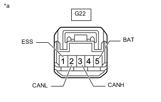
*a Front view of wire harness connector
(to Spiral with Sensor Cable Sub-assembly [Steering Angle Sensor])
Disconnect the spiral with sensor cable sub-assembly (steering angle sensor) connector.
-
Measure the resistance according to the value(s) in the table below.
Terminal No. (Symbol) Wiring Color Terminal Description Condition Specified Condition G22-3 (CANH) - G22-2 (CANL) BE - W HIGH-level CAN bus wire - LOW-level CAN bus wire Cable disconnected from negative (-) battery terminal 54 to 69 Ω G22-3 (CANH) - G22-1 (ESS) BE - BR HIGH-level CAN bus wire - GND Cable disconnected from negative (-) battery terminal 200 Ω or higher G22-2 (CANL) - G22-1 (ESS) W - BR LOW-level CAN bus wire - GND Cable disconnected from negative (-) battery terminal 200 Ω or higher G22-3 (CANH) - G22-5 (BAT) BE - W HIGH-level CAN bus wire - Battery positive (+) Cable disconnected from negative (-) battery terminal 6 kΩ or higher G22-2 (CANL) - G22-5 (BAT) W - W LOW-level CAN bus wire - Battery positive (+) Cable disconnected from negative (-) battery terminal 6 kΩ or higher
-
-
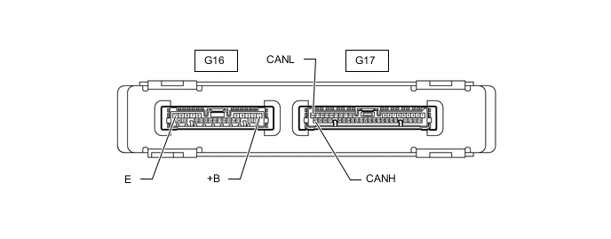
CHECK CERTIFICATION ECU (SMART KEY ECU ASSEMBLY) (w/ Smart Entry and Start System)
-
Disconnect the certification ECU (smart key ECU assembly) connectors.
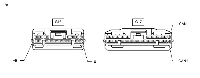
*a Front view of wire harness connector
(to Certification ECU [Smart Key ECU Assembly])
- - -
Measure the resistance according to the value(s) in the table below.
Terminal No. (Symbol) Wiring Color Terminal Description Condition Specified Condition G17-40 (CANH) - G17-18 (CANL) G - W HIGH-level CAN bus wire - LOW-level CAN bus wire Cable disconnected from negative (-) battery terminal 54 to 69 Ω G17-40 (CANH) - G16-10 (E) G - BR HIGH-level CAN bus wire - GND Cable disconnected from negative (-) battery terminal 200 Ω or higher G17-18 (CANL) - G16-10 (E) W - BR LOW-level CAN bus wire - GND Cable disconnected from negative (-) battery terminal 200 Ω or higher G17-40 (CANH) - G16-1 (+B) G - P HIGH-level CAN bus wire - Battery positive (+) Cable disconnected from negative (-) battery terminal 6 kΩ or higher G17-18 (CANL) - G16-1 (+B) W - P LOW-level CAN bus wire - Battery positive (+) Cable disconnected from negative (-) battery terminal 6 kΩ or higher
-
-
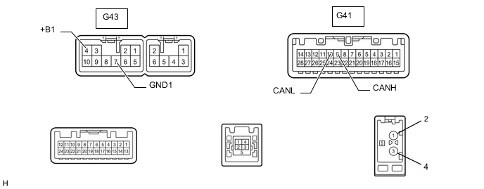
CHECK NAVIGATION RECEIVER ASSEMBLY (w/ Navigation System)
-
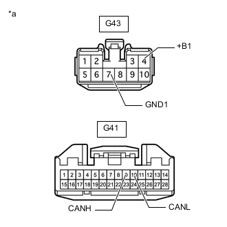
*a Front view of wire harness connector
(to Navigation Receiver assembly)
Disconnect the navigation receiver assembly connectors.
-
Measure the resistance according to the value(s) in the table below.
Terminal No. (Symbol) Wiring Color Terminal Description Condition Specified Condition G41-9 (CANH) - G41-10 (CANL) V - W HIGH-level CAN bus wire - LOW-level CAN bus wire Cable disconnected from negative (-) battery terminal 54 to 69 Ω G41-9 (CANH) - G43-7 (GND1) V - BR HIGH-level CAN bus wire - GND Cable disconnected from negative (-) battery terminal 200 Ω or higher G41-10 (CANL) - G43-7 (GND1) W - BR LOW-level CAN bus wire - GND Cable disconnected from negative (-) battery terminal 200 Ω or higher G41-9 (CANH) - G43-4 (+B1) V - SB HIGH-level CAN bus wire - Battery positive (+) Cable disconnected from negative (-) battery terminal 6 kΩ or higher G41-10 (CANL) - G43-4 (+B1) W - SB LOW-level CAN bus wire - Battery positive (+) Cable disconnected from negative (-) battery terminal 6 kΩ or higher
-
-
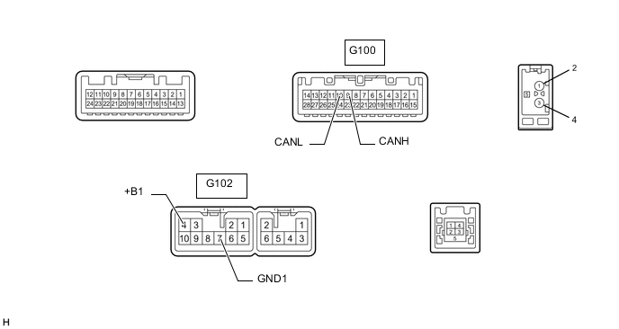
CHECK RADIO AND DISPLAY RECEIVER ASSEMBLY (w/ Audio and Visual System)
-

*a Front view of wire harness connector
(to Radio and Display Receiver Assembly)
Disconnect the radio and display receiver assembly connectors.
-
Measure the resistance according to the value(s) in the table below.
Terminal No. (Symbol) Wiring Color Terminal Description Condition Specified Condition G100-9 (CANH) - G100-10 (CANL) V - W HIGH-level CAN bus wire - LOW-level CAN bus wire Cable disconnected from negative (-) battery terminal 54 to 69 Ω G100-9 (CANH) - G102-7 (GND1) V - BR HIGH-level CAN bus wire - GND Cable disconnected from negative (-) battery terminal 200 Ω or higher G100-10 (CANL) - G102-7 (GND1) W - BR LOW-level CAN bus wire - GND Cable disconnected from negative (-) battery terminal 200 Ω or higher G100-9 (CANH) - G102-4 (+B1) V - SB HIGH-level CAN bus wire - Battery positive (+) Cable disconnected from negative (-) battery terminal 6 kΩ or higher G100-10 (CANL) - G102-4 (+B1) W - SB LOW-level CAN bus wire - Battery positive (+) Cable disconnected from negative (-) battery terminal 6 kΩ or higher
-
-
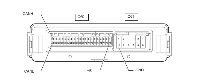
CHECK 4 WHEEL DRIVE CONTROL ECU (for 4WD)
-
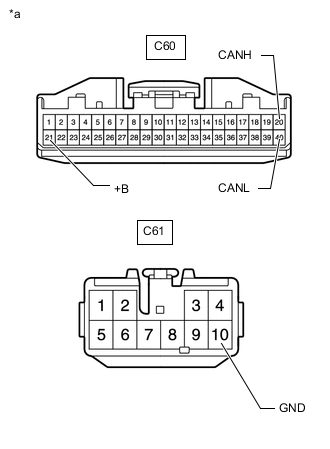
*a Front view of wire harness connector
(to 4 Wheel Drive Control ECU)
Disconnect the 4 wheel drive control ECU connectors.
-
Measure the resistance according to the value(s) in the table below.
Terminal No. (Symbol) Wiring Color Terminal Description Condition Specified Condition C60-20 (CANH) - C60-40 (CANL) R - W HIGH-level CAN bus wire - LOW-level CAN bus wire Cable disconnected from negative (-) battery terminal 54 to 69 Ω C60-20 (CANH) - C61-10 (GND) R - W-B HIGH-level CAN bus wire - GND Cable disconnected from negative (-) battery terminal 200 Ω or higher C60-40 (CANL) - C61-10 (GND) W - W-B LOW-level CAN bus wire - GND Cable disconnected from negative (-) battery terminal 200 Ω or higher C60-20 (CANH) - C60-21 (+B) R - L HIGH-level CAN bus wire - Battery positive (+) Cable disconnected from negative (-) battery terminal 6 kΩ or higher C60-40 (CANL) - C60-21 (+B) W - L LOW-level CAN bus wire - Battery positive (+) Cable disconnected from negative (-) battery terminal 6 kΩ or higher
-
-
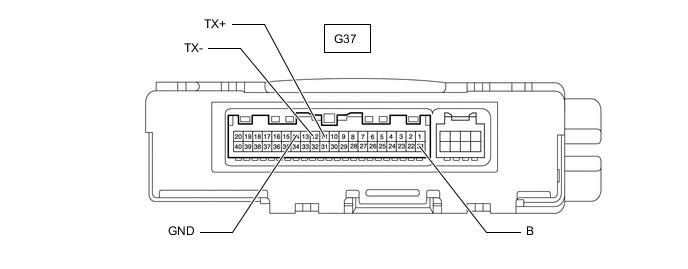
CHECK AIR CONDITIONING AMPLIFIER ASSEMBLY (for Automatic Air Conditioning System)
-
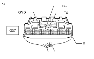
*a Rear view of wire harness connector
(to Air Conditioning Amplifier Assembly)
Disconnect the air conditioning amplifier assembly connector.
-
Measure the resistance according to the value(s) in the table below.
Terminal No. (Symbol) Wiring Color Terminal Description Condition Specified Condition G37-11 (TX+) - G37-12 (TX-) GR - W HIGH-level CAN bus wire - LOW-level CAN bus wire Cable disconnected from negative (-) battery terminal 54 to 69 Ω G37-11 (TX+) - G37-14 (GND) GR - W-B HIGH-level CAN bus wire - GND Cable disconnected from negative (-) battery terminal 200 Ω or higher G37-12 (TX-) - G37-14 (GND) W - W-B LOW-level CAN bus wire - GND Cable disconnected from negative (-) battery terminal 200 Ω or higher G37-11 (TX+) - G37-21 (B) GR - W HIGH-level CAN bus wire - Battery positive (+) Cable disconnected from negative (-) battery terminal 6 kΩ or higher G37-12 (TX-) - G37-21 (B) W - W LOW-level CAN bus wire - Battery positive (+) Cable disconnected from negative (-) battery terminal 6 kΩ or higher
-
-
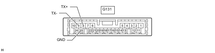
CHECK AIR CONDITIONING AMPLIFIER ASSEMBLY (for Manual Air Conditioning System)
-
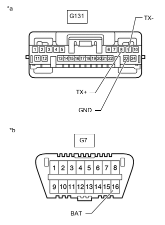
*a Front view of wire harness connector
(to Air Conditioning Amplifier Assembly)
*b Front view of DLC3 Disconnect the air conditioning amplifier assembly connector.
-
Measure the resistance according to the value(s) in the table below.
Terminal No. (Symbol) Wiring Color Terminal Description Condition Specified Condition G131-8 (TX+) - G131-9 (TX-) GR - W HIGH-level CAN bus wire - LOW-level CAN bus wire Cable disconnected from negative (-) battery terminal 54 to 69 Ω G131-8 (TX+) - G131-23 (GND) GR - W-B HIGH-level CAN bus wire - GND Cable disconnected from negative (-) battery terminal 200 Ω or higher G131-9 (TX-) - G131-23 (GND) W - W-B LOW-level CAN bus wire - GND Cable disconnected from negative (-) battery terminal 200 Ω or higher G131-8 (TX+) - G7-16 (BAT) GR - G HIGH-level CAN bus wire - Battery positive (+) Cable disconnected from negative (-) battery terminal 6 kΩ or higher G131-9 (TX-) - G7-16 (BAT) W - G LOW-level CAN bus wire - Battery positive (+) Cable disconnected from negative (-) battery terminal 6 kΩ or higher
-
-
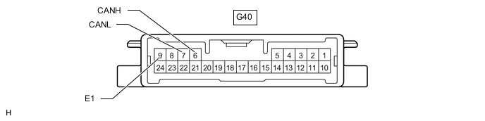
CHECK HEADLIGHT LEVELING ECU ASSEMBLY (for LED Headlight)
-
*a Front view of wire harness connector
(to Headlight Leveling ECU Assembly)
*b Front view of DLC3 Disconnect the headlight leveling ECU assembly connector.
-
Measure the resistance according to the value(s) in the table below.
Terminal No. (Symbol) Wiring Color Terminal Description Condition Specified Condition G40-6 (CANH) - G40-7 (CANL) V - W HIGH-level CAN bus wire - LOW-level CAN bus wire Cable disconnected from negative (-) battery terminal 54 to 69 Ω G40-6 (CANH) - G40-9 (E1) V - W-B HIGH-level CAN bus wire - GND Cable disconnected from negative (-) battery terminal 200 Ω or higher G40-7 (CANL) - G40-9 (E1) W - W-B LOW-level CAN bus wire - GND Cable disconnected from negative (-) battery terminal 200 Ω or higher G40-6 (CANH) - G7-16 (BAT) V - G HIGH-level CAN bus wire - Battery positive (+) Cable disconnected from negative (-) battery terminal 6 kΩ or higher G40-7 (CANL) - G7-16 (BAT) W - G LOW-level CAN bus wire - Battery positive (+) Cable disconnected from negative (-) battery terminal 6 kΩ or higher
-
-
CHECK MULTIPLEX NETWORK DOOR ECU (w/ Back Door Closer System)
-
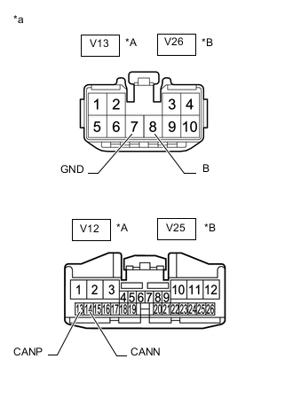
*A w/ Power Back Door System *B w/o Power Back Door System *a Front view of wire harness connector
(to Multiplex Network Door ECU)
Disconnect the multiplex network door ECU connectors.
-
Measure the resistance according to the value(s) in the table below.
w/ Power Back Door System Terminal No. (Symbol) Wiring Color Terminal Description Condition Specified Condition V12-13 (CANP) - V12-14 (CANN) SB - W HIGH-level CAN bus wire - LOW-level CAN bus wire Cable disconnected from negative (-) battery terminal 54 to 69 Ω V12-13 (CANP) - V13-7 (GND) SB - W-B HIGH-level CAN bus wire - GND Cable disconnected from negative (-) battery terminal 200 Ω or higher V12-14 (CANN) - V13-7 (GND) W - W-B LOW-level CAN bus wire - GND Cable disconnected from negative (-) battery terminal 200 Ω or higher V12-13 (CANP) - V13-8 (B) SB - G HIGH-level CAN bus wire - Battery positive (+) Cable disconnected from negative (-) battery terminal 6 kΩ or higher V12-14 (CANN) - V13-8 (B) W - G LOW-level CAN bus wire - Battery positive (+) Cable disconnected from negative (-) battery terminal 6 kΩ or higher w/o Power Back Door System Terminal No. (Symbol) Wiring Color Terminal Description Condition Specified Condition V25-13 (CANP) - V25-14 (CANN) SB - W HIGH-level CAN bus wire - LOW-level CAN bus wire Cable disconnected from negative (-) battery terminal 54 to 69 Ω V25-13 (CANP) - V26-7 (GND) SB - W-B HIGH-level CAN bus wire - GND Cable disconnected from negative (-) battery terminal 200 Ω or higher V25-14 (CANN) - V26-7 (GND) W - W-B LOW-level CAN bus wire - GND Cable disconnected from negative (-) battery terminal 200 Ω or higher V25-13 (CANP) - V26-8 (B) SB - G HIGH-level CAN bus wire - Battery positive (+) Cable disconnected from negative (-) battery terminal 6 kΩ or higher V25-14 (CANN) - V26-8 (B) W - G LOW-level CAN bus wire - Battery positive (+) Cable disconnected from negative (-) battery terminal 6 kΩ or higher
-
-
CHECK TELEMATICS TRANSCEIVER (w/ Telematics Transceiver)
Refer to Terminals of ECU.
-
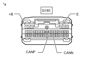
*a Front view of wire harness connector
(to Telematics Transceiver)
Disconnect the telematics transceiver connector.
-
Measure the resistance according to the value(s) in the table below.
Terminal No. (Symbol) Wiring Color Terminal Description Condition Specified Condition G180-15 (CANP) - G180-16 (CANN) P - W HIGH-level CAN bus wire - LOW-level CAN bus wire Cable disconnected from negative (-) battery terminal 54 to 69 Ω G180-15 (CANP) - G180-4 (E) P - W-B HIGH-level CAN bus wire - GND Cable disconnected from negative (-) battery terminal 200 Ω or higher G180-16 (CANN) - G180-4 (E) W - W-B LOW-level CAN bus wire - GND Cable disconnected from negative (-) battery terminal 200 Ω or higher G180-15 (CANP) - G180-1 (+B) P - V HIGH-level CAN bus wire - Battery positive (+) Cable disconnected from negative (-) battery terminal 6 kΩ or higher G180-16 (CANN) - G180-1 (+B) W - V LOW-level CAN bus wire - Battery positive (+) Cable disconnected from negative (-) battery terminal 6 kΩ or higher
-