CAN COMMUNICATION SYSTEM(for RHD) SYSTEM DESCRIPTION
-
BRIEF DESCRIPTION
-
The Controller Area Network (CAN) is a serial data communication system for real time application. It is a vehicle multiplex communication system which has a high communication speed and the ability to detect malfunctions.
-
Using the CANH and CANL bus wires as a pair, CAN communication is performed using a voltage differential. (A base voltage is applied to the pair of wires and a voltage differential is created when communicating.)
-
Many ECUs or sensors installed on the vehicle operate by sharing information and communicating with each other.
-
The CAN has two resistors of 120 Ω which are necessary to enable communication.
-
-
DEFINITION OF TERMS
-
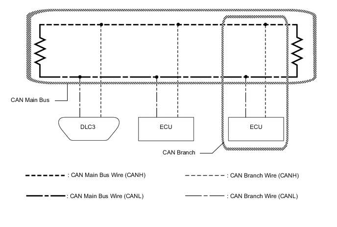
CAN main wire
-
The CAN main wire is a wire harness between the 2 termination circuits on the bus (communication wire). This is the main bus in the CAN communication system.
-
-
CAN branch wire
-
The CAN branch wire is a wire harness which diverges from the main wire to an ECU or sensor.
-
-
Termination circuits
-
Two resistors of 120 Ω are installed in parallel across the ends of the CAN main bus wires. They are called terminating resistors. These resistors allow the changes of the voltage differential between the CAN bus wires to be accurately judged. To allow proper function of CAN communication, it is necessary to have both terminating resistors installed. Since the two resistors are installed in parallel, this results in a measurement of approximately 60 Ω.
-
-
-
ECUS OR SENSORS WHICH COMMUNICATE VIA CAN COMMUNICATION SYSTEM
-
V Bus
-
ECM
-
Brake actuator assembly (skid control ECU)
-
Spiral with sensor cable sub-assembly (steering angle sensor)*6
-
Air conditioning amplifier assembly
-
Airbag sensor assembly
-
Certification ECU (smart key ECU assembly)*1
-
4 wheel drive control ECU*7
-
Navigation receiver assembly*2
-
Radio and display receiver assembly*3
-
Headlight leveling ECU assembly*4
-
Multiplex network door ECU*5
-
DLC3
-
Combination meter assembly
-
*1: w/ Smart Entry and Start System
-
*2: w/ Navigation System
-
*3: w/ Audio and Visual System
-
*4: for LED Headlight
-
*5: w/ Back Door Closer System
-
*6: w/ VSC
-
*7: for 4WD
-
-
-
-
CIRCUIT DESCRIPTION
-
The V bus has termination circuits with a resistance of 120 Ω x 2. High speed communication at 500 kbps is possible.
-
-
TROUBLESHOOTING REMARKS
-
DTCs for the CAN communication system can be checked using the GTS. The DLC3 is connected to the CAN communication system, but no DTCs exist regarding problems in the DLC3 or the DLC3 branch wires. If there is a malfunction in the DLC3 or the DLC3 branch wires, ECUs on the CAN cannot output DTCs to the GTS.
-
Malfunctions in the CAN V bus (communication wires) can be checked by measuring the resistance between terminals of the DLC3. However, an open circuit in a branch wire other than the DLC3 branch wires cannot be checked from the DLC3 (except for the DLC3 branch wires).
Note
Do not insert the tester probes directly into the DLC3. Be sure to use service wires.
-
-
DIAGNOSTIC TROUBLE CODES FOR CAN COMMUNICATION SYSTEM
-
DIAGNOSTIC TROUBLE CODES FOR CAN COMMUNICATION SYSTEM
-
In the CAN communication system, the shape of all connectors connected to the CAN junction connector is the same.
The connectors connected to the CAN junction connector can be distinguished by the colors of the bus wire and the connecting side of the connector.
Tech Tips
Refer to "Terminals of ECU" for bus wire color or the connecting side of the connector.
-