LIN COMMUNICATION SYSTEM TERMINALS OF ECU
-
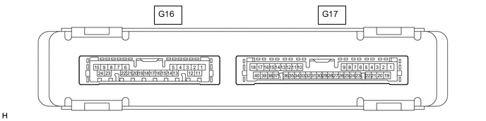
CHECK CERTIFICATION ECU (SMART KEY ECU ASSEMBLY)
-
Disconnect the G16 certification ECU connector.
-
Measure the resistance and voltage according to the value(s) in the table below.
Terminal No. (Symbol) Wiring Color Terminal Description Condition Specified Condition G16-1 (+B) - Body ground P - Body ground Battery power supply Always 11 to 14 V G16-10 (E) - Body ground BR - Body ground Ground Always Below 1 Ω
-
-
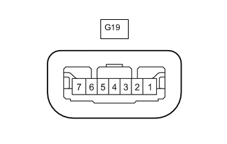
CHECK STEERING LOCK ACTUATOR OR UPPER BRACKET ASSEMBLY
-
Disconnect the G19 steering lock actuator or upper assembly connector.
-
Measure the resistance and voltage according to the value(s) in the table below.
Terminal No. (Symbol) Wiring Color Terminal Description Condition Specified Condition G19-7 (B) - Body ground W - Body ground Battery power supply Always 11 to 14 V G19-1 (GND) - Body ground W-B - Body ground Ground Always Below 1 Ω
-
-
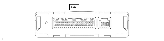
CHECK AIR CONDITIONING AMPLIFIER ASSEMBLY (for Automatic Air Conditioning System)
-
Disconnect the G37 air conditioning amplifier assembly connector.
-
Measure the resistance and voltage according to the value(s) in the table below.
Terminal No. (Symbol) Wiring Color Terminal Description Condition Specified Condition G37-1 (IG+) - Body ground G - Body ground IG power supply Engine switch off Below 1 V G37-1 (IG+) - Body ground G - Body ground IG power supply Engine switch on (IG) 11 to 14 V G37-21 (B) - Body ground W - Body ground Battery power supply Always 11 to 14 V G37-14 (GND) - Body ground W-B - Body ground Ground Always Below 1 Ω
-
-
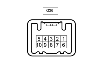
CHECK AIR CONDITIONING CONTROL ASSEMBLY (for Automatic Air Conditioning System)
-
Disconnect the G36 air conditioning control assembly connector.
-
Measure the resistance and voltage according to the value(s) in the table below.
Terminal No. (Symbol) Wiring Color Terminal Description Condition Specified Condition G36-2 (IG+) - Body ground L - Body ground IG power supply Engine switch on (IG) 11 to 14 V G36-2 (IG+) - Body ground L - Body ground IG power supply Engine switch off Below 1 V G36-4 (GND) - Body ground W-B - Body ground Ground Always Below 1 Ω
-
-
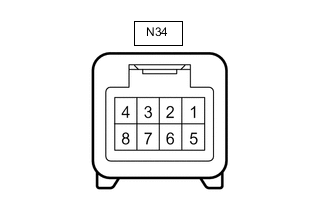
INTEGRATION CONTROL AND PANEL ASSEMBLY (for Automatic Air Conditioning System)
-
Disconnect the N34 integration control and panel assembly connector.
-
Measure the resistance and voltage according to the value(s) in the table below.
Terminal No. (Symbol) Wiring Color Terminal Description Condition Specified Condition N34-8 (IG+) - Body ground G - Body ground IG power supply Engine switch on (IG) 11 to 14 V G - Body ground IG power supply Engine switch off Below 1 V N34-5 (GND) - Body ground W-B - Body ground Ground Always Below 1 Ω
-
-
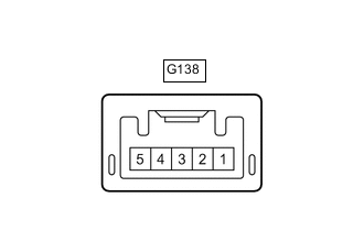
CHECK ID CODE BOX (IMMOBILISER CODE ECU) (w/ ID Code Box [Immobiliser Code ECU])
-
Disconnect the G138 ID code box connector.
-
Measure the resistance and voltage according to the value(s) in the table below.
Terminal No. (Symbol) Wiring Color Terminal Description Condition Specified Condition G138-1 (+B) - Body ground L - Body ground Battery power supply Always 11 to 14 V G138-5 (GND) - Body ground BR - Body ground Ground Always Below 1 Ω
-