GENERATOR INSPECTION

PROCEDURE
-
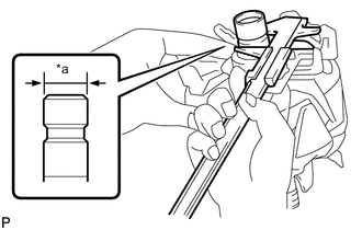
INSPECT GENERATOR BRUSH HOLDER ASSEMBLY
-
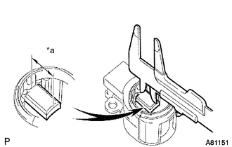
*a Length Using a vernier caliper, measure the brush length.
Standard length 9.5 to 11.5 mm (0.374 to 0.453 in.) Minimum length 4.5 mm (0.177 in.) If the length is less than the minimum, replace the generator brush holder assembly.
-
-
INSPECT GENERATOR ROTOR ASSEMBLY
-
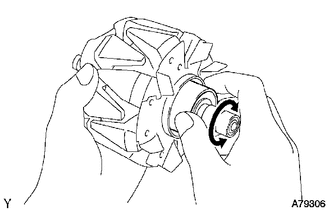
Check that the generator rotor bearing is not rough or worn and that it rotates smoothly.
If necessary, replace the generator rotor assembly.
-
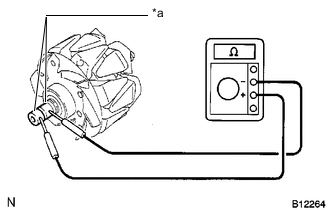
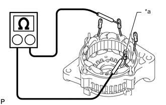
*a Slip Ring Check the generator rotor assembly for an open circuit.
-
Measure the resistance according to the value(s) in the table below.
Standard Resistance Tester Connection Condition Specified Condition Slip ring - Slip ring 20°C (68°F) 2.1 to 2.5 Ω If the result is not as specified, replace the generator rotor assembly.
-
-
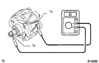
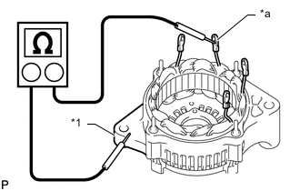
*a Rotor Core *b Slip Ring Check if the generator rotor assembly is grounded.
-
Measure the resistance according to the value(s) in the table below.
Standard Resistance Tester Connection Condition Specified Condition Rotor core - Slip ring Always 10 MΩ or higher If the result is not as specified, replace the generator rotor assembly.
-
-
Check each slip ring.
-
Check that the slip rings are not rough or scored.
If the slip rings are rough or scored, replace the generator rotor assembly.
-
*a Diameter Using a vernier caliper, measure the slip ring diameter.
Standard diameter 14.2 to 14.8 mm (0.559 to 0.583 in.) Minimum diameter 14.0 mm (0.551 in.) If the diameter is less than the minimum, replace the generator rotor assembly.
-
-
-
INSPECT GENERATOR DRIVE END FRAME
-
*a Coil Lead Check the stator for an open circuit.
-
Measure the resistance according to the value(s) in the table below.
Standard Resistance Tester Connection Condition Specified Condition Coil lead - Coil lead Always Below 1 Ω If the result is not as specified, replace the generator assembly.
-
-
*1 Generator Drive End Frame *a Coil Lead Check the stator for a short circuit.
-
Measure the resistance according to the value(s) in the table below.
Standard Resistance Tester Connection Condition Specified Condition Coil lead - Generator drive end frame Always 10 MΩ or higher If the result is not as specified, replace the generator assembly.
-
-
Inspect the generator drive end frame bearing.
-
Check that the generator drive end frame bearing is not rough or worn.
If necessary, replace the generator assembly.
-
-
-
INSPECT GENERATOR HOLDER WITH RECTIFIER
-
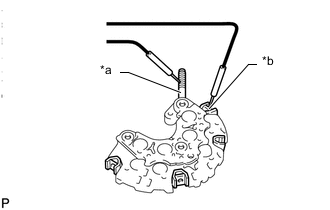
*a Terminal B *b Rectifier Terminal Check the positive terminal of the generator holder with rectifier.
-
Using an ohmmeter, connect one tester probe to the terminal B and the other to each rectifier terminal.
-
Reverse the polarity of the tester probes and repeat the step above.
-
Measure the resistance according to the value(s) in the table below.
Standard Resistance Tester Connection Condition Specified Condition Terminal B - one polarity Always Below 1 Ω Terminal B - other polarity Always 10 MΩ or higher If the result is not as specified, replace the generator holder with rectifier.
-
-
*a Negative (-) Terminal Check the negative (-) terminal of the generator holder with rectifier.
-
Using an ohmmeter, connect one tester probe to the negative (-) terminal and the other to each rectifier terminal.
-
Reverse the polarity of the tester probes and repeat the step above.
-
Measure the resistance according to the value(s) in the table below.
Standard Resistance Tester Connection Condition Specified Condition Negative (-) terminal - one polarity Always Below 1 Ω Negative (-) terminal - other polarity Always 10 MΩ or higher If the result is not as specified, replace the generator holder with rectifier.
-
-
-
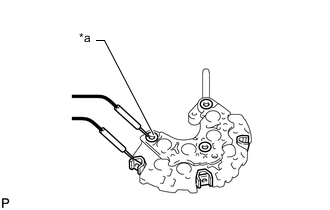
INSPECT GENERATOR REGULATOR ASSEMBLY
-
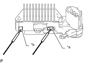
*a Terminal F *b Terminal B Measure the resistance according to the value(s) in the table below.
Standard Resistance Tester Connection Condition Specified Condition Terminal F - Terminal B Always Below 1 Ω or higher than 10 MΩ If the result is not as specified, replace the generator regulator assembly.
Tech Tips
When the ohmmeter leads are initially touched to the regulator, one of the above values is output.
When the leads are reversed, the reading changes to the other value.
-
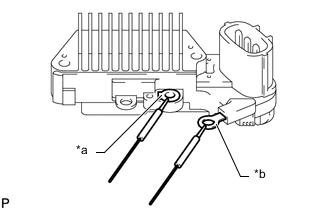
*a Terminal F *b Terminal E Measure the resistance according to the value(s) in the table below.
Standard Resistance Tester Connection Condition Specified Condition Terminal F - Terminal E Always Below 1 Ω or higher than 10 MΩ If the result is not as specified, replace the generator regulator assembly.
Tech Tips
When the ohmmeter leads are initially touched to the regulator, one of the above values is output.
When the leads are reversed, the reading changes to the other value.
-