TOYOTA PARKING ASSIST-SENSOR SYSTEM Illumination Circuit
DESCRIPTION
Power is supplied to the back sonar or clearance sonar switch assembly illumination when the light control switch is in the tail or head position.
WIRING DIAGRAM
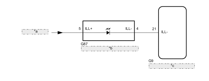
| *a | from TAIL Relay |
| *b | Back Sonar or Clearance Sonar Switch Assembly |
| *c | Combination Meter Assembly |
CAUTION / NOTICE / HINT
Note
-
Inspect the relay for circuits related to this system before performing the following procedure.
-
When replacing the combination meter assembly, make sure to replace it with a new one.
PROCEDURE
-
CHECK ILLUMINATION
-
Check if the illumination for the back sonar or clearance sonar switch assembly, heater control switch or others (hazard switch, transmission control switch, etc.) comes on when the light control switch is turned to the tail or head position.
Result Result Proceed to Illumination comes on for all components except back sonar or clearance sonar switch assembly A No illumination comes on (back sonar or clearance sonar switch assembly, hazard switch, heater control switch, etc.) B
B 
GO TO LIGHTING SYSTEM Click here
A 
-
-
INSPECT BACK SONAR OR CLEARANCE SONAR SWITCH ASSEMBLY
-
Remove the back sonar or clearance sonar switch assembly.
-
Inspect the back sonar or clearance sonar switch assembly.
Result Proceed to OK NG
NG
REPLACE BACK SONAR OR CLEARANCE SONAR SWITCH ASSEMBLY Click here
OK
-
-
CHECK HARNESS AND CONNECTOR (BACK SONAR OR CLEARANCE SONAR SWITCH ASSEMBLY ILLUMINATION SIGNAL)
-
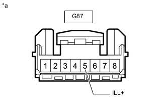
*a Front view of wire harness connector
(to Back Sonar or Clearance Sonar Switch Assembly)
Disconnect the back sonar or clearance sonar switch assembly connector.
-
Measure the voltage according to the value(s) in the table below.
Standard Voltage Tester Connection Condition Specified Condition G87-5 (ILL+) - Body ground Light control switch in tail or head position 11 to 14 V Result Proceed to OK NG
NG
REPAIR OR REPLACE HARNESS OR CONNECTOR
OK
-
-
CHECK HARNESS AND CONNECTOR (BACK SONAR OR CLEARANCE SONAR SWITCH ASSEMBLY - COMBINATION METER ASSEMBLY)
-
Disconnect the G87 back sonar or clearance sonar switch assembly connector.
-
Disconnect the G9 combination meter assembly connector.
-
Measure the resistance according to the value(s) in the table below.
Standard Resistance Tester Connection Condition Specified Condition G87-4 (ILL-) - G9-21 (ILL-) Always Below 1 Ω G87-4 (ILL-) or G9-21 (ILL-) - Body ground Always 10 kΩ or higher Result Proceed to OK NG
OK
REPLACE COMBINATION METER ASSEMBLY Click here
NG
REPAIR OR REPLACE HARNESS OR CONNECTOR
-