TOYOTA PARKING ASSIST-SENSOR SYSTEM TERMINALS OF ECU
-
CLEARANCE WARNING ECU ASSEMBLY

-
Disconnect the G88 clearance warning ECU assembly connector.
-
Measure the voltage and resistance according to the value(s) in the table below.
Terminal No. (Symbol) Wiring Color Terminal Description Condition Specified Condition G88-11 (IG) - Body ground R - Body ground IG power source signal
-
Ignition switch to ON
-
Back sonar or clearance sonar switch assembly off
Below 1 V
-
Ignition switch to ON
-
Back sonar or clearance sonar switch assembly on
11 to 14 V G88-16 (E) - Body ground BR - Body ground Ground Always Below 1 Ω G88-21 (RL) - Body ground R - Body ground Reverse position signal
-
Ignition switch to ON
-
Shift lever in any position other than R
Below 1 V
-
Ignition switch to ON
-
Shift lever in R
11 to 14 V -
-
Reconnect the G88 clearance warning ECU assembly connector.
-
Measure the voltage and resistance, and check for pulses according to the value(s) in the table below.
Terminal No. (Symbol) Wiring Color Terminal Description Condition Specified Condition G88-2 (ER) - Body ground B - Body ground Clearance warning buzzer signal When sonar detects obstacle (buzzer sounds) Pulse generation
(See waveform 1)
G88-1 (BBZ) - Body ground W - Body ground Power source of clearance warning buzzer
-
Ignition switch to ON
-
Back sonar or clearance sonar switch assembly on
11 to 14 V G88-12 (BOR) - Body ground V - Body ground Power source for rear center sensor circuit Ignition switch off. Below 1 V
-
Ignition switch to ON
-
Back sonar or clearance sonar switch assembly on
7.2 to 8.8 V G88-13 (E1) - Body ground L - Body ground Ground for sensor (Rear center sensor) Always Below 1 Ω G88-14 (SOR) - Body ground G - Body ground Sensor communication signal (Rear center sensor)
-
Ignition switch to ON
-
Back sonar or clearance sonar switch assembly on
-
Shift lever in R
Pulse generation
(See waveform 2)
-
-
Using an oscilloscope, check waveform.
-
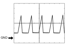
Waveform 1 (Reference)
Item Content Terminal No. (Symbol) G88-2 (ER) - Body ground Tool Setting 2 V/DIV., 200 μsec./DIV. Vehicle Condition When sonar detects obstacle (buzzer sounds) -
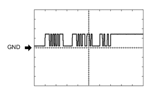
Waveform 2 (Reference)
Item Content Terminal No. (Symbol) G88-14 (SOR) - Body ground Tool Setting 5 V/DIV., 1 msec./DIV. Condition
-
Ignition switch to ON
-
Back sonar or clearance sonar switch assembly on
-
Shift lever in R
-
-
-