TOYOTA PARKING ASSIST-SENSOR SYSTEM Clearance Warning Buzzer Circuit
DESCRIPTION
This circuit consists of the No. 1 clearance warning buzzer and clearance warning ECU assembly. An ECU-excited type buzzer is used. The ECU operates the buzzer using a sound pattern that changes depending on the distance to an obstacle.
WIRING DIAGRAM
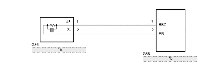
| *a | No. 1 Clearance Warning Buzzer |
| *b | Clearance Warning ECU Assembly |
PROCEDURE
-
CHECK CLEARANCE WARNING ECU ASSEMBLY (BUZZER CIRCUIT)
-
Remove the clearance warning ECU assembly with its connectors still connected.
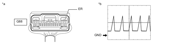
*a Component with harness connected
(Clearance Warning ECU Assembly)
*b Waveform -
Check the waveform of the clearance warning ECU assembly using an oscilloscope.
Item Content Terminal No. (Symbol) G88-2 (ER) - Body ground Tool Setting 2 V/DIV., 200 μsec./DIV. Condition When sonar detects obstacle (buzzer sounds) OK Waveform is as shown in the illustration. Result Proceed to OK NG
OK 
REPLACE CLEARANCE WARNING ECU ASSEMBLY Click here
NG 
-
-
CHECK HARNESS AND CONNECTOR (CLEARANCE WARNING ECU ASSEMBLY - NO. 1 CLEARANCE WARNING BUZZER)
-
Disconnect the G88 clearance warning ECU assembly connector.
-
Disconnect the G86 No. 1 clearance warning buzzer connector.
-
Measure the resistance according to the value(s) in the table below.
Standard Resistance Tester Connection Condition Specified Condition G88-1 (BBZ) - G86-1 (Z+) Always Below 1 Ω G88-2 (ER) - G86-2 (Z-) Always Below 1 Ω G88-1 (BBZ) or G86-1 (Z+) - Body ground Always 10 kΩ or higher G88-2 (ER) or G86-2 (Z-) - Body ground Always 10 kΩ or higher Result Proceed to OK NG
NG
REPAIR OR REPLACE HARNESS OR CONNECTOR
OK
-
-
CHECK NO. 1 CLEARANCE WARNING BUZZER
-
Replace the No. 1 clearance warning buzzer with a new or known good one.
-
Check if the same malfunction recurs when the sonar function is operated.
OK Malfunction does not reoccur (returns to normal). Result Proceed to OK NG
OK
END (NO. 1 CLEARANCE WARNING BUZZER WAS DEFECTIVE)
NG
REPLACE CLEARANCE WARNING ECU ASSEMBLY Click here
-