TOYOTA PARKING ASSIST-SENSOR SYSTEM Back Sonar Sensor Circuit
DESCRIPTION
This circuit consists of the sensor power supply, sensor ground and sensor signal wires between the clearance warning ECU assembly and ultrasonic sensors. The ultrasonic sensors are digital sensors.
WIRING DIAGRAM
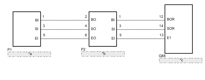
| *a | No. 1 Ultrasonic Sensor (Rear Left Center) |
| *b | No. 1 Ultrasonic Sensor (Rear Right Center) |
| *c | Clearance Warning ECU Assembly |
PROCEDURE
-
CHECK HARNESS AND CONNECTOR (CLEARANCE WARNING ECU ASSEMBLY - NO. 1 ULTRASONIC SENSOR [REAR RIGHT CENTER])
-
Disconnect the G88 clearance warning ECU assembly connector.
-
Disconnect the P2 No. 1 ultrasonic sensor (rear right center) connector.
-
Measure the resistance according to the value(s) in the table below.
Standard Resistance Tester Connection Condition Specified Condition G88-12 (BOR) - P2-1 (BI) Always Below 1 Ω G88-14 (SOR) - P2-3 (SI) Always Below 1 Ω G88-13 (E1) - P2-5 (EI) Always Below 1 Ω G88-12 (BOR) or P2-1 (BI) - Body ground Always 10 kΩ or higher G88-14 (SOR) or P2-3 (SI) - Body ground Always 10 kΩ or higher G88-13 (E1) or P2-5 (EI) - Body ground Always 10 kΩ or higher Result Proceed to OK NG
NG 
REPAIR OR REPLACE HARNESS OR CONNECTOR
OK 
-
-
CHECK HARNESS AND CONNECTOR (NO. 1 ULTRASONIC SENSOR [REAR RIGHT CENTER] - NO. 1 ULTRASONIC SENSOR [REAR LEFT CENTER])
-
Disconnect the P2 No. 1 ultrasonic sensor (rear right center) connector.
-
Disconnect the P1 No. 1 ultrasonic sensor (rear left center) connector.
-
Measure the resistance according to the value(s) in the table below.
Standard Resistance Tester Connection Condition Specified Condition P2-2 (BO) - P1-1 (BI) Always Below 1 Ω P2-4 (SO) - P1-3 (SI) Always Below 1 Ω P2-6 (EO) - P1-5 (EI) Always Below 1 Ω P2-2 (BO) or P1-1 (BI) - Body ground Always 10 kΩ or higher P2-4 (SO) or P1-3 (SI) - Body ground Always 10 kΩ or higher P2-6 (EO) or P1-5 (EI) - Body ground Always 10 kΩ or higher Result Proceed to OK NG
NG
REPAIR OR REPLACE HARNESS OR CONNECTOR
OK
-
-
INSPECT NO. 1 ULTRASONIC SENSOR (REAR RIGHT SIDE, REAR LEFT SIDE)
-
Remove the No. 1 ultrasonic sensor.
-
Inspect the No. 1 ultrasonic sensor.
Result Proceed to OK NG
OK
PROCEED TO NEXT SUSPECTED AREA SHOWN IN PROBLEM SYMPTOMS TABLE Click here
NG
REPLACE NO. 1 ULTRASONIC SENSOR Click here
-