NAVIGATION SYSTEM Speaker Circuit
DESCRIPTION
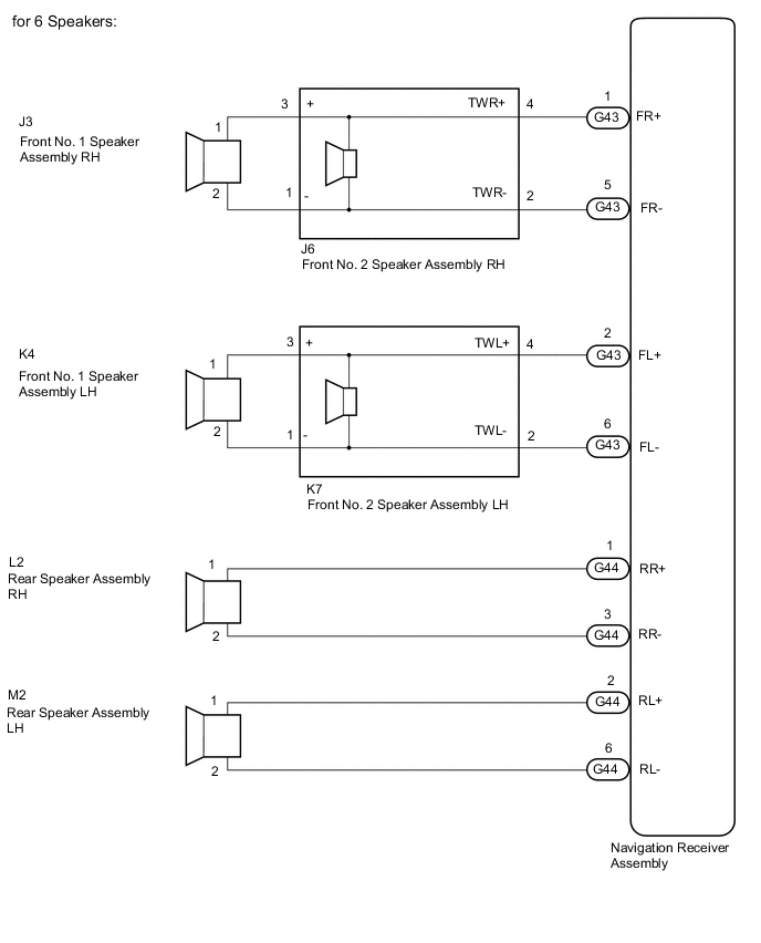
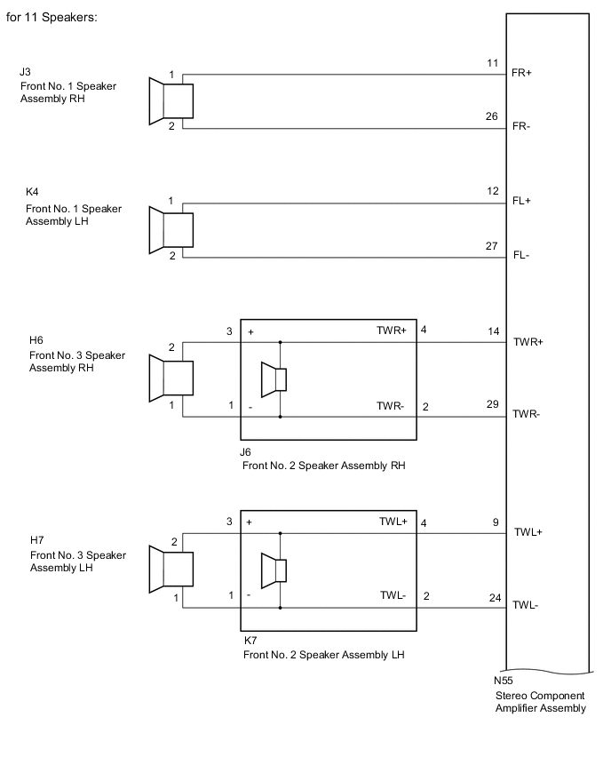
The sound signals amplified by the navigation receiver assembly*1 or stereo component amplifier assembly*2 are sent to the speakers from the navigation receiver assembly*1 or stereo component amplifier assembly*2 via the speaker circuit.
If there is a short in a speaker circuit, the navigation receiver assembly*1 or stereo component amplifier assembly*2 detects it and stops output to the speakers.
Thus sound cannot be heard from the speakers even if there is no malfunction in the navigation receiver assembly*1, stereo component amplifier assembly*2 or speakers.
-
*1: for 6 Speakers
-
*2: for 11 Speakers
WIRING DIAGRAM
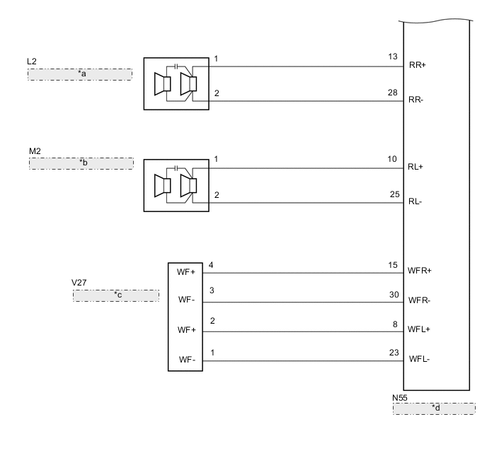
| *a | Rear Speaker Assembly RH |
| *b | Rear Speaker Assembly LH |
| *c | Rear No. 3 Speaker Assembly |
| *d | Stereo Component Amplifier Assembly |
CAUTION / NOTICE / HINT
Note
Check that the wire harness is properly installed and does not have any sharp bends, pinching or loose connections.
PROCEDURE
-
CHECK VEHICLE CONDITION
-
Check the vehicle condition.
Result Result Proceed to for 6 Speakers A for 11 Speakers B
B 
CHECK HARNESS AND CONNECTOR (SPEAKER CIRCUIT) Click here
A 
-
-
CHECK HARNESS AND CONNECTOR (SPEAKER CIRCUIT)
-
*1: for LH Side
-
*2: for RH Side
-
Disconnect the G43 and G44 navigation receiver assembly connectors.
-
Disconnect the K4*1 and/or J3*2 front No. 1 speaker assembly connector.
-
Disconnect the K7*1 and/or J6*2 front No. 2 speaker assembly connector.
-
Disconnect the M2*1 and/or L2*2 rear speaker assembly connector.
-
Measure the resistance according to the value(s) in the table below.
Standard Resistance for LH Side Tester Connection Condition Specified Condition G43-2 (FL+) - K7-4 (TWL+) Always Below 1 Ω G43-6 (FL-) - K7-2 (TWL-) Always Below 1 Ω K7-3 (+) - K4-1 Always Below 1 Ω K7-1 (-) - K4-2 Always Below 1 Ω G44-2 (RL+) - M2-1 Always Below 1 Ω G44-6 (RL-) - M2-2 Always Below 1 Ω G43-2 (FL+) - Body ground Always 10 kΩ or higher G43-6 (FL-) - Body ground Always 10 kΩ or higher G44-2 (RL+) - Body ground Always 10 kΩ or higher G44-6 (RL-) - Body ground Always 10 kΩ or higher K7-3 (+) - Body ground Always 10 kΩ or higher K7-1 (-) - Body ground Always 10 kΩ or higher for RH Side Tester Connection Condition Specified Condition G43-1 (FR+) - J6-4 (TWR+) Always Below 1 Ω G43-5 (FR-) - J6-2 (TWR-) Always Below 1 Ω J6-3 (+) - J3-1 Always Below 1 Ω J6-1 (-) - J3-2 Always Below 1 Ω G44-1 (RR+) - L2-1 Always Below 1 Ω G44-3 (RR-) - L2-2 Always Below 1 Ω G43-1 (FR+) - Body ground Always 10 kΩ or higher G43-5 (FR-) - Body ground Always 10 kΩ or higher G44-1 (RR+) - Body ground Always 10 kΩ or higher G44-3 (RR-) - Body ground Always 10 kΩ or higher J6-3 (+) - Body ground Always 10 kΩ or higher J6-1 (-) - Body ground Always 10 kΩ or higher Result Proceed to OK NG
NG 
REPAIR OR REPLACE HARNESS OR CONNECTOR
OK
-
-
INSPECT FRONT NO. 1 SPEAKER ASSEMBLY
-
Remove the front No. 1 speaker assembly connector.
-
Inspect the front No. 1 speaker assembly.
Result Proceed to OK NG
NG
REPLACE FRONT NO. 1 SPEAKER ASSEMBLY Click here
OK
-
-
INSPECT REAR SPEAKER ASSEMBLY
-
Remove the rear speaker assembly connector.
-
Inspect the rear speaker assembly.
Result Proceed to OK NG
NG
REPLACE REAR SPEAKER ASSEMBLY Click here
OK
-
-
CHECK FRONT NO. 2 SPEAKER ASSEMBLY
-
Replace the front No. 2 speaker assembly with a known good one.
-
Check the malfunction disappears.
Tech Tips
-
Connect all the connectors to the front No. 2 speaker assemblies that were disconnected.
-
When there is a possibility that either the right or left front speaker is defective, inspect by interchanging the right one with the left one.
-
Perform the above inspection on both LH and RH sides.
OK Malfunction disappears. Result Proceed to OK NG -
OK
END (FRONT NO. 2 SPEAKER ASSEMBLY IS DEFECTIVE)
NG
REPLACE NAVIGATION RECEIVER ASSEMBLY Click here
-
-
CHECK HARNESS AND CONNECTOR (SPEAKER CIRCUIT)
-
*1: for LH Side
-
*2: for RH Side
-
Disconnect the N55 stereo component amplifier assembly connector.
-
Disconnect the K4*1 and/or J3*2 front No. 1 speaker assembly connector.
-
Disconnect the K7*1 and/or J6*2 front No. 2 speaker assembly connector.
-
Disconnect the H7*1 and/or H6*2 front No. 3 speaker assembly connector.
-
Disconnect the M2*1 and/or L2*2 rear speaker assembly connector.
-
Disconnect the V27 rear No. 3 speaker assembly connector.
-
Measure the resistance according to the value(s) in the table below.
Standard Resistance for LH Side Tester Connection Condition Specified Condition N55-12 (FL+) - K4-1 Always Below 1 Ω N55-27 (FL-) - K4-2 Always Below 1 Ω N55-9 (TWL+) - K7-4 (TWL+) Always Below 1 Ω N55-24 (TWL-) - K7-2 (TWL-) Always Below 1 Ω K7-3 (+) - H7-2 Always Below 1 Ω K7-1 (-) - H7-1 Always Below 1 Ω N55-10 (RL+) - M2-1 Always Below 1 Ω N55-25 (RL-) - M2-2 Always Below 1 Ω N55-12 (FL+) - Body ground Always 10 kΩ or higher N55-27 (FL-) - Body ground Always 10 kΩ or higher N55-9 (TWL+) - Body ground Always 10 kΩ or higher N55-24 (TWL-) - Body ground Always 10 kΩ or higher K7-3 (+) - Body ground Always 10 kΩ or higher K7-1 (-) - Body ground Always 10 kΩ or higher N55-10 (RL+) - Body ground Always 10 kΩ or higher N55-25 (RL-) - Body ground Always 10 kΩ or higher for RH Side Tester Connection Condition Specified Condition N55-11 (FR+) - J3-1 Always Below 1 Ω N55-26 (FR-) - J3-2 Always Below 1 Ω N55-14 (TWR+) - J6-4 (TWR+) Always Below 1 Ω N55-29 (TWR-) - J6-2 (TWR-) Always Below 1 Ω J6-3 (+) - H6-2 Always Below 1 Ω J6-1 (-) - H6-1 Always Below 1 Ω N55-13 (RR+) - L2-1 Always Below 1 Ω N55-28 (RR-) - L2-2 Always Below 1 Ω N55-11 (FR+) - Body ground Always 10 kΩ or higher N55-26 (FR-) - Body ground Always 10 kΩ or higher N55-14 (TWR+) - Body ground Always 10 kΩ or higher N55-29 (TWR-) - Body ground Always 10 kΩ or higher J6-3 (+) - Body ground Always 10 kΩ or higher J6-1 (-) - Body ground Always 10 kΩ or higher N55-13 (RR+) - Body ground Always 10 kΩ or higher N55-28 (RR-) - Body ground Always 10 kΩ or higher for Rear No. 3 Speaker Assembly Tester Connection Condition Specified Condition N55-15 (WFR+) - V27-4 (WF+) Always Below 1 Ω N55-30 (WFR-) - V27-3 (WF-) Always Below 1 Ω N55-8 (WFL+) - V27-2 (WF+) Always Below 1 Ω N55-23 (WFL-) - V27-1 (WF-) Always Below 1 Ω N55-15 (WFR+) - Body ground Always 10 kΩ or higher N55-30 (WFR-) - Body ground Always 10 kΩ or higher N55-8 (WFL+) - Body ground Always 10 kΩ or higher N55-23 (WFL-) - Body ground Always 10 kΩ or higher Result Proceed to OK NG
NG
REPAIR OR REPLACE HARNESS OR CONNECTOR
OK
-
-
INSPECT FRONT NO. 1 SPEAKER ASSEMBLY
-
Remove the front No. 1 speaker assembly connector.
-
Inspect the front No. 1 speaker assembly.
Result Proceed to OK NG
NG
REPLACE FRONT NO. 1 SPEAKER ASSEMBLY Click here
OK
-
-
INSPECT FRONT NO. 3 SPEAKER ASSEMBLY
-
Remove the front No. 3 speaker assembly connector.
-
Inspect the front No. 3 speaker assembly.
Result Proceed to OK NG
NG
REPLACE FRONT NO. 3 SPEAKER ASSEMBLY Click here
OK
-
-
INSPECT REAR SPEAKER ASSEMBLY
-
Remove the rear speaker assembly connector.
-
Inspect the rear speaker assembly.
Result Proceed to OK NG
NG
REPLACE REAR SPEAKER ASSEMBLY Click here
OK
-
-
INSPECT REAR NO. 3 SPEAKER ASSEMBLY
-
Remove the rear No. 3 speaker assembly connector.
-
Inspect the rear No. 3 speaker assembly.
Result Proceed to OK NG
NG
REPLACE REAR NO. 3 SPEAKER ASSEMBLY Click here
OK
-
-
CHECK FRONT NO. 2 SPEAKER ASSEMBLY
-
Replace the front No. 2 speaker assembly with a known good one.
-
Check the malfunction disappears.
Tech Tips
-
Connect all the connectors to the front No. 2 speaker assemblies that were disconnected.
-
When there is a possibility that either the right or left front speaker is defective, inspect by interchanging the right one with the left one.
-
Perform the above inspection on both LH and RH sides.
OK Malfunction disappears. Result Proceed to OK NG -
OK
END (FRONT NO. 2 SPEAKER ASSEMBLY IS DEFECTIVE)
NG
-
-
CHECK STEREO COMPONENT AMPLIFIER ASSEMBLY
-
Replace the stereo component amplifier assembly with a known good one.
-
Check the malfunction disappears.
OK Malfunction disappears. Result Proceed to OK NG
OK
END (STEREO COMPONENT AMPLIFIER ASSEMBLY IS DEFECTIVE)
NG
REPLACE NAVIGATION RECEIVER ASSEMBLY Click here
-