RADIO RECEIVER REMOVAL
CAUTION / NOTICE / HINT
The necessary procedures (adjustment, calibration, initialization or registration) that must be performed after parts are removed, installed or replaced during the radio receiver removal/installation are shown below.
| Replacement Part or Procedure | Necessary Procedures | Effects/Inoperative when not Performed | Link |
|---|---|---|---|
| Disconnect cable from negative battery terminal | w/ Power Back Door System: Reset back door close position |
Power back door system |
CAUTION:
Some of these service operations affect the SRS airbag system. Read the precautionary notices concerning the SRS airbag system before servicing.
PROCEDURE
-
PRECAUTION
Note
After turning the ignition switch off, waiting time may be required before disconnecting the cable from the battery terminal. Therefore, make sure to read the disconnecting the cable from the battery terminal notice before proceeding with work Click here.
-
DISCONNECT CABLE FROM NEGATIVE BATTERY TERMINAL
CAUTION:
Wait at least 90 seconds after disconnecting the cable from the negative (-) battery terminal to disable the SRS system.
Note
When disconnecting the cable, some systems need to be initialized after the cable is reconnected Click here.
-
REMOVE INSTRUMENT PANEL REGISTER BEZEL GARNISH
-
REMOVE NO. 1 INSTRUMENT PANEL GARNISH SUB-ASSEMBLY
-
REMOVE NO. 2 INSTRUMENT PANEL GARNISH SUB-ASSEMBLY
-
REMOVE CENTER INSTRUMENT CLUSTER FINISH PANEL SUB-ASSEMBLY
-
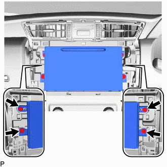
REMOVE RADIO RECEIVER ASSEMBLY WITH BRACKET
-
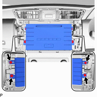
Remove the 4 screws.
-
Pull out the radio receiver assembly with bracket.
-
Disconnect all the connectors and remove the radio receiver assembly with bracket.
-
-
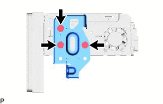
REMOVE NO. 1 RADIO BRACKET
-
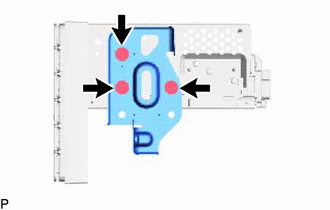
Remove the 3 screws and No. 1 radio bracket from the radio receiver assembly.
-
-
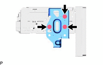
REMOVE NO. 2 RADIO BRACKET
-
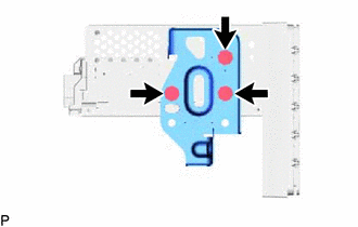
Remove the 3 screws and No. 2 radio bracket from the radio receiver assembly.
-
-
REMOVE RADIO RECEIVER ASSEMBLY
-
REMOVE RADIO AND DISPLAY RECEIVER ASSEMBLY WITH BRACKET
-
Remove the 4 screws.
-
Pull out the radio and display receiver assembly with bracket.
-
Disconnect all the connectors and remove the radio and display receiver assembly with bracket.
-
-
REMOVE NO. 1 RADIO BRACKET
-
Remove the 3 screws and No. 1 radio bracket from the radio and display receiver assembly.
-
-
REMOVE NO. 2 RADIO BRACKET
-
Remove the 3 screws and No. 2 radio bracket from the radio and display receiver assembly.
-
-
REMOVE RADIO AND DISPLAY RECEIVER ASSEMBLY