AUDIO AND VISUAL SYSTEM(for Radio and Display Type) Dimmer Signal Circuit
DESCRIPTION
The combination meter assembly sends an auto dimmer signal to the radio and display receiver assembly via this circuit.
When the radio and display receiver assembly receives an auto dimmer signal from the combination meter assembly, the panel switch of the radio and display receiver assembly dims and the screen changes to the night screen.
WIRING DIAGRAM
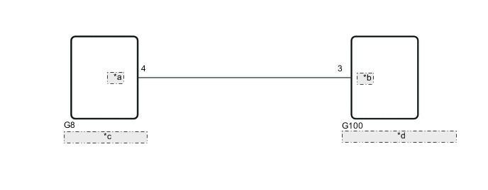
| *a | ACAN |
| *b | ADIM |
| *c | Combination Meter Assembly |
| *d | Radio and Display Receiver Assembly |
CAUTION / NOTICE / HINT
Note
When replacing the combination meter assembly, make sure to replace it with a new one.
PROCEDURE
-
CHECK COMBINATION METER ASSEMBLY (DIMMER SIGNAL)
-
Disconnect the radio and display receiver assembly connector.
-
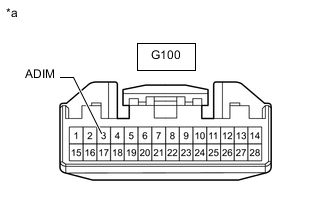
*a Front view of wire harness connector
(to Radio and Display Receiver Assembly)
Measure the voltage according to the value(s) in the table below.
Standard Voltage Tester Connection Condition Specified Condition G100-3 (ADIM) - Body ground Ignition switch ON, automatic light control sensor covered by hand, and light control switch in tail or head position 11 to 14 V Ignition switch ON, automatic light control sensor not covered by hand, and light control switch in auto position Below 1 V Result Proceed to OK NG
OK 
PROCEED TO NEXT SUSPECTED AREA SHOWN IN PROBLEM SYMPTOMS TABLE Click here
NG 
-
-
CHECK HARNESS AND CONNECTOR (RADIO AND DISPLAY RECEIVER ASSEMBLY - COMBINATION METER ASSEMBLY)
-
Disconnect the G100 radio and display receiver assembly connector.
-
Disconnect the G8 combination meter assembly connector.
-
Measure the resistance according to the value(s) in the table below.
Standard Resistance Tester Connection Condition Specified Condition G100-3 (ADIM) - G8-4 (ACAN) Always Below 1 Ω G100-3 (ADIM) or G8-4 (ACAN) - Body ground Always 10 kΩ or higher Result Proceed to OK NG
OK
REPLACE COMBINATION METER ASSEMBLY Click here
NG
REPAIR OR REPLACE HARNESS OR CONNECTOR
-