AUDIO AND VISUAL SYSTEM(for Radio and Display Type), Diagnostic DTC:B15C3
| DTC Code | DTC Name |
|---|---|
| B15C3 | Speaker Output Short |
DESCRIPTION
This DTC is stored when a malfunction occurs in the speakers.
| DTC No. | Detection Item | DTC Detection Condition | Trouble Area |
|---|---|---|---|
| B15C3 | Speaker Output Short | A short is detected in the speaker output circuit |
|
-
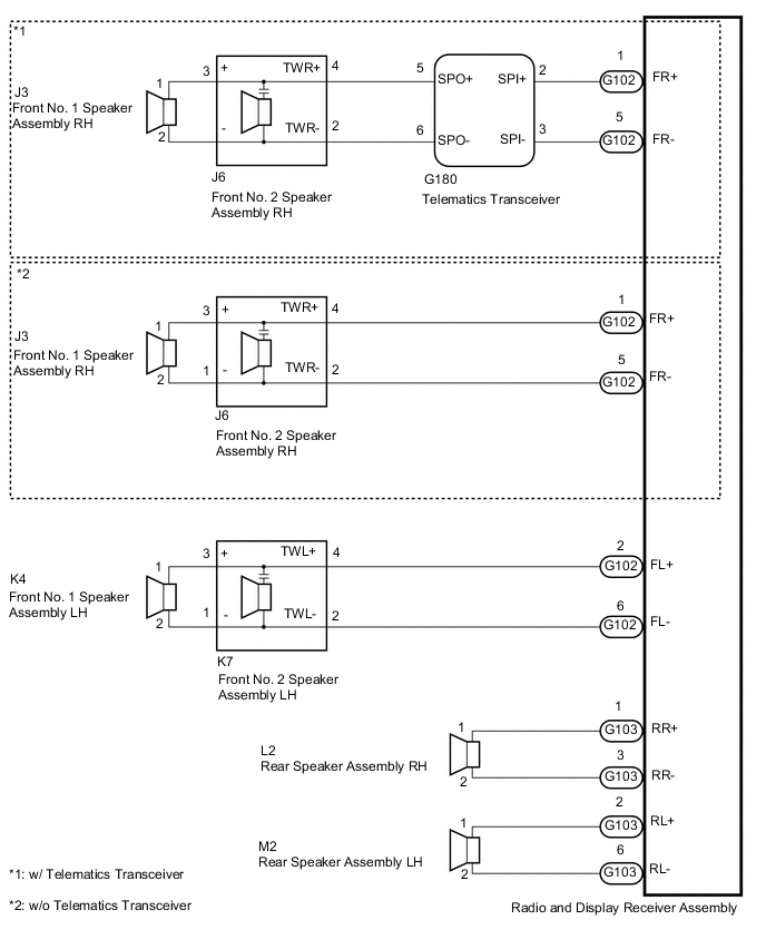
*: w/ Telematics Transceiver
WIRING DIAGRAM
PROCEDURE
-
CHECK DTC
-
Clear the DTCs.
Body Electrical > Navigation System > Clear DTCs -
Recheck for DTCs and check that no DTCs are output.
Body Electrical > Navigation System > Trouble CodesOK No DTCs are output. Result Proceed to OK NG
OK 
USE SIMULATION METHOD TO CHECK Click here
NG 
-
-
CHECK VEHICLE CONDITION
-
Check the vehicle condition.
Result Result Proceed to w/o Telematics Transceiver A w/ Telematics Transceiver B
B 
CHECK HARNESS AND CONNECTOR (SPEAKER CIRCUIT) Click here
A
-
-
CHECK HARNESS AND CONNECTOR (SPEAKER CIRCUIT)
-
*1: for LH Side
*2: for RH Side
-
Disconnect the G102 and G103 radio and display receiver assembly connectors.
-
Disconnect the K4*1 and/or J3*2 front No. 1 speaker assembly connector.
-
Disconnect the K7*1 and/or J6*2 front No. 2 speaker assembly connector.
-
Disconnect the M2*1 and/or L2*2 rear speaker assembly connector.
-
Measure the resistance according to the value(s) in the table below.
Standard Resistance for LH Side: Tester Connection Condition Specified Condition G102-2 (FL+) - K7-4 (TWL+) Always Below 1 Ω G102-6 (FL-) - K7-2 (TWL-) Always Below 1 Ω K7-3 (+) - K4-1 Always Below 1 Ω K7-1 (-) - K4-2 Always Below 1 Ω G103-2 (RL+) - M2-1 Always Below 1 Ω G103-6 (RL-) - M2-2 Always Below 1 Ω G102-2 (FL+) - Body ground Always 10 kΩ or higher G102-6 (FL-) - Body ground Always 10 kΩ or higher K7-3 (+) - Body ground Always 10 kΩ or higher K7-1 (-) - Body ground Always 10 kΩ or higher G103-2 (RL+) - Body ground Always 10 kΩ or higher G103-6 (RL-) - Body ground Always 10 kΩ or higher for RH Side: Tester Connection Condition Specified Condition G102-1 (FR+) - J6-4 (TWR+) Always Below 1 Ω G102-5 (FR-) - J6-2 (TWR-) Always Below 1 Ω J6-3 (+) - J3-1 Always Below 1 Ω J6-1 (-) - J3-2 Always Below 1 Ω G103-1 (RR+) - L2-1 Always Below 1 Ω G103-3 (RR-) - L2-2 Always Below 1 Ω G102-1 (FR+) - Body ground Always 10 kΩ or higher G102-5 (FR-) - Body ground Always 10 kΩ or higher J6-3 (+) - Body ground Always 10 kΩ or higher J6-1 (-) - Body ground Always 10 kΩ or higher G103-1 (RR+) - Body ground Always 10 kΩ or higher G103-3 (RR-) - Body ground Always 10 kΩ or higher Result Proceed to OK NG
NG
REPAIR OR REPLACE HARNESS OR CONNECTOR
OK
-
-
INSPECT FRONT NO. 1 SPEAKER ASSEMBLY
-
Remove the front No. 1 speaker assembly.
-
Inspect the front No. 1 speaker assembly.
Result Proceed to OK NG
NG
REPLACE FRONT NO. 1 SPEAKER ASSEMBLY Click here
OK
-
-
INSPECT REAR SPEAKER ASSEMBLY
-
Remove the rear speaker assembly.
-
Inspect the rear speaker assembly.
Result Proceed to OK NG
NG
REPLACE REAR SPEAKER ASSEMBLY Click here
OK
-
-
CHECK FRONT NO. 2 SPEAKER ASSEMBLY
-
Replace the front No. 2 speaker assembly.
-
Check the malfunction disappears.
OK Malfunction disappears. Tech Tips
-
Connect all the connectors to the rear No. 2 speaker assemblies that were disconnected.
-
When there is a possibility that either the right or left front speaker is defective, inspect by interchanging the right one with the left one.
-
Perform the above inspection on both the LH and RH sides.
Result Proceed to OK NG -
OK
END (FRONT NO. 2 SPEAKER ASSEMBLY IS DEFECTIVE)
NG
PROCEED TO NEXT SUSPECTED AREA SHOWN IN PROBLEM SYMPTOMS TABLE Click here
-
-
CHECK HARNESS AND CONNECTOR (SPEAKER CIRCUIT)
-
*1: for LH Side
*2: for RH Side
-
Disconnect the G102 and G103 radio and display receiver assembly connectors.
-
Disconnect the K4*1 and/or J3*2 front No. 1 speaker assembly connector.
-
Disconnect the K7*1 and/or J6*2 front No. 2 speaker assembly connector.
-
Disconnect the M2*1 and/or L2*2 rear speaker assembly connector.
-
Disconnect the G180 telematics transceiver connector.
-
Measure the resistance according to the value(s) in the table below.
Standard Resistance for LH Side: Tester Connection Condition Specified Condition G102-2 (FL+) - K7-4 (TWL+) Always Below 1 Ω G102-6 (FL-) - K7-2 (TWL-) Always Below 1 Ω K7-3 (+) - K4-1 Always Below 1 Ω K7-1 (-) - K4-2 Always Below 1 Ω G103-2 (RL+) - M2-1 Always Below 1 Ω G103-6 (RL-) - M2-2 Always Below 1 Ω G102-2 (FL+) - Body ground Always 10 kΩ or higher G102-6 (FL-) - Body ground Always 10 kΩ or higher K7-3 (+) - Body ground Always 10 kΩ or higher K7-1 (-) - Body ground Always 10 kΩ or higher G103-2 (RL+) - Body ground Always 10 kΩ or higher G103-6 (RL-) - Body ground Always 10 kΩ or higher for RH Side: Tester Connection Condition Specified Condition G102-1 (FR+) - G180-2 (SPI+) Always Below 1 Ω G102-5 (FR-) - G180-3 (SPI-) Always Below 1 Ω G180-5 (SPO+) - J6-4 (TWR+) Always Below 1 Ω G180-6 (SPO-) - J6-2 (TWR-) Always Below 1 Ω J6-3 (+) - J3-1 Always Below 1 Ω J6-1 (-) - J3-2 Always Below 1 Ω G103-1 (RR+) - L2-1 Always Below 1 Ω G103-3 (RR-) - L2-2 Always Below 1 Ω G102-1 (FR+) - Body ground Always 10 kΩ or higher G102-5 (FR-) - Body ground Always 10 kΩ or higher G180-5 (SPO+) - Body ground Always 10 kΩ or higher G180-6 (SPO-) - Body ground Always 10 kΩ or higher J6-3 (+) - Body ground Always 10 kΩ or higher J6-1 (-) - Body ground Always 10 kΩ or higher G103-1 (RR+) - Body ground Always 10 kΩ or higher G103-3 (RR-) - Body ground Always 10 kΩ or higher Result Proceed to OK NG
NG
REPAIR OR REPLACE HARNESS OR CONNECTOR
OK
-
-
INSPECT FRONT NO. 1 SPEAKER ASSEMBLY
-
Remove the front No. 1 speaker assembly.
-
Inspect the front No. 1 speaker assembly.
Result Proceed to OK NG
NG
REPLACE FRONT NO. 1 SPEAKER ASSEMBLY Click here
OK
-
-
INSPECT REAR SPEAKER ASSEMBLY
-
Remove the rear speaker assembly.
-
Inspect the rear speaker assembly.
Result Proceed to OK NG
NG
REPLACE REAR SPEAKER ASSEMBLY Click here
OK
-
-
CHECK FRONT NO. 2 SPEAKER ASSEMBLY
-
Replace the front No. 2 speaker assembly.
-
Check the malfunction disappears.
OK Malfunction disappears. Tech Tips
-
Connect all the connectors to the rear No. 2 speaker assemblies that were disconnected.
-
When there is a possibility that either the right or left front speaker is defective, inspect by interchanging the right one with the left one.
-
Perform the above inspection on both the LH and RH sides.
Result Proceed to OK NG -
OK
END (FRONT NO. 2 SPEAKER ASSEMBLY IS DEFECTIVE)
NG
-
-
CHECK TELEMATICS TRANSCEIVER
-
Replace the telematics transceiver with a new one.
-
Check the malfunction disappears.
OK Malfunction disappears. Result Proceed to OK NG
OK
END (TELEMATICS TRANSCEIVER IS DEFECTIVE)
NG
REPLACE RADIO AND DISPLAY RECEIVER ASSEMBLY Click here
-