AUDIO AND VISUAL SYSTEM(for Radio and Display Type) TERMINALS OF ECU
-
RADIO AND DISPLAY RECEIVER ASSEMBLY
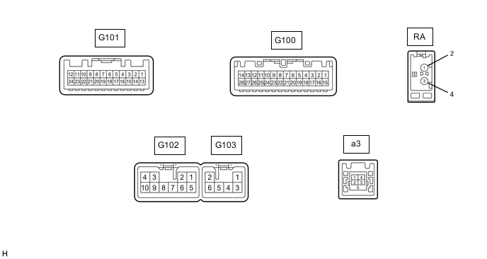
Terminal No. (Symbol) Wiring Color Terminal Description Condition Specification G100-1 (IG) - G102-7 (GND1) G - BR Power source (IG) Ignition switch off Below 1 V Ignition switch ON 11 to 14 V G100-2 (REV) - G102-7 (GND1) R - BR Reverse signal See "Check Vehicle Signal" in Operation Check
- G100-3 (ADIM) - G102-7 (GND1) W - BR Illumination (auto dimmer) signal Ignition switch ON, automatic light control sensor not covered by hand, and light control switch in auto position Below 1 V Ignition switch ON, automatic light control sensor covered by hand, and light control switch in auto position 11 to 14 V G100-4 (MACC) - G102-7 (GND1) B - BR Telephone microphone assembly power supply Ignition switch off Below 1 V Ignition switch ACC 4 to 6 V G100-5 (MIN+) - G102-7 (GND1) W - BR Telephone microphone assembly voice signal See "Check Microphone" in Operation Check
- G100-6 (SNS2) - G102-7 (GND1) W-B - BR Ground Always Below 1 V G100-9 (CANH) V CAN communication signal - - G100-10 (CANL) W CAN communication signal - - G100-11 (AGND) - Body ground Shielded - Body ground Shielded ground Always Below 1 V G100-12 (SG) - Body ground Shielded - Body ground Shielded ground Always Below 1 V G100-13 (VV+) - G102-7 (GND1) B - BR Video signal External device playing (When stereo jack used) A waveform synchronized with video signals is output G100-14 (VV-) - G102-7 (GND1) W - BR Video signal External device playing (When stereo jack used) A waveform synchronized with video signals is output G100-15 (PKB) - G102-7 (GND1) V - BR Parking brake signal See "Check Vehicle Signal" in Operation Check
- G100-17 (SPD) - G102-7 (GND1) V - BR Vehicle speed signal See "Check Vehicle Signal" in Operation Check
- G100-18 (SGND) - Body ground Shielded - Body ground Shielded ground Always Below 1 V G100-19 (MIN-) - G102-7 (GND1) R - BR Telephone microphone assembly voice signal See "Check Microphone" in Operation Check
- G100-21 (SW1) - G100-23 (SWG) Y - V Steering pad switch signal No switch pushed 2.97 to 3.56 V Seek+ switch pushed 0.27 to 0.35 V Seek- switch pushed 0.86 to 1.03 V Volume+ switch pushed 1.51 to 1.79 V Volume- switch pushed 2.22 to 2.66 V G100-22 (SW2) - G100-23 (SWG) G - V Steering pad switch signal No switch pushed 2.97 to 3.56 V MODE switch pushed 0.27 to 0.35 V On hook switch pushed 0.86 to 1.03 V Off hook switch pushed 1.51 to 1.79 V Voice switch pushed 2.22 to 2.66 V G100-23 (SWG) - G102-7 (GND1) V - BR Steering pad switch ground Always Below 1 V G100-25 (ADPG) - G102-7 (GND1) G - BR External device connection detection signal External device connected Below 1 V External device not connected 2.1 to 3 V G100-26 (VAR+) - G100-27 (VA-) B - W Sound signal (Right) External device playing (When stereo jack used) A waveform synchronized with sound signals is output G100-27 (VA-) - G102-7 (GND1) W - BR Ground Always Below 1 V G100-28 (VAL+) - G100-27 (VA-) R - W Sound signal (Left) External device playing (When stereo jack used) A waveform synchronized with sound signals is output G101-3 (CNH1) B Local CAN communication signal - - G101-4 (CNL1) W Local CAN communication signal - - G102-1 (FR+) - G102-7 (GND1) LG - BR Sound signal (Front Right) Audio system playing A waveform synchronized with sound signals is output G102-2 (FL+) - G102-7 (GND1) P - BR Sound signal (Front Left) Audio system playing A waveform synchronized with sound signals is output G102-3 (ACC1) - G102-7 (GND1) GR - BR Power source (ACC) Ignition switch off Below 1 V Ignition switch ACC 11 to 14 V G102-4 (+B1) - G102-7 (GND1) SB - BR Power source (+B) Always 11 to 14 V G102-5 (FR-) - G102-7 (GND1) L - BR Sound signal (Front Right) Audio system playing A waveform synchronized with sound signals is output G102-6 (FL-) - G102-7 (GND1) V - BR Sound signal (Front Left) Audio system playing A waveform synchronized with sound signals is output G102-7 (GND1) - Body ground BR - Body ground Ground Always Below 1 Ω G102-10 (ILL+) - G102-7 (GND1) G - BR Illumination signal Light control switch off Below 1 V Light control switch in tail or head position 11 to 14 V G103-1 (RR+) - G102-7 (GND1) R - BR Sound signal (Rear Right) Audio system playing A waveform synchronized with voice signals is output G103-2 (RL+) - G102-7 (GND1) B - BR Sound signal (Rear Left) Audio system playing A waveform synchronized with voice signals is output G103-3 (RR-) - G102-7 (GND1) W - BR Sound signal (Rear Right) Audio system playing A waveform synchronized with voice signals is output G103-5 (ILL-) - G102-7 (GND1) W-B - BR Illumination signal Light control switch off Below 1 V Light control switch in tail or head position Pulse generation G103-6 (RL-) - G102-7 (GND1) Y - BR Sound signal (Rear Left) Audio system playing A waveform synchronized with voice signals is output a3-1 (USV1) # Power source - - a3-2 (US1-) # Data signal - - a3-3 (US1+) # Data signal - - a3-4 (UGD1) # Ground - - a3-5 (USG1) Shielded Shielded ground - - RA-5 (ANT+) - G102-7 (GND1) # - BR Power source of antenna Ignition switch ACC, radio switch on and FM or AM selected 11 to 14 V #: There is no wire color information