FRONT DOOR ADJUSTMENT

CAUTION / NOTICE / HINT
The necessary procedures (adjustment, calibration, initialization or registration) that must be performed after parts are removed, installed or replaced during the front door adjustment are shown below.
| Replacement Part or Procedure | Necessary Procedures | Effects / Inoperative when not Performed | Link |
|---|---|---|---|
| Disconnect cable from negative battery terminal |
w/ Power Back Door System: |
Power back door system |
Tech Tips
-
Use the same procedure for the RH and LH sides.
-
The procedure listed below is for the RH side.
-
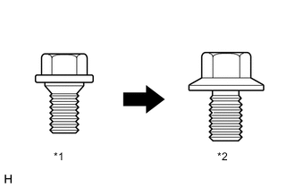
*1 Centering Bolt *2 Standard Bolt Centering bolts are used to mount the door hinge to the vehicle body and door. The door cannot be adjusted with the centering bolts on. Substitute the centering bolts for standard bolts when making adjustments.
-
A bolt without a torque specification is shown in the standard bolt chart.
PROCEDURE
-
PRECAUTION
Note
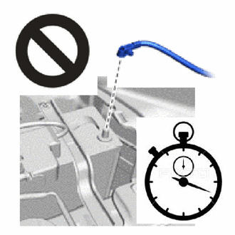
After turning the ignition switch off, waiting time may be required before disconnecting the cable from the negative (-) battery terminal. Therefore, make sure to read the disconnecting the cable from the negative (-) battery terminal notice before proceeding with work.
-
DISCONNECT CABLE FROM NEGATIVE BATTERY TERMINAL
CAUTION:
-
Wait at least 90 seconds after disconnecting the cable from the negative (-) battery terminal to disable the SRS system.
-
If the airbag deploys for any reason, it may cause a serious accident.
Note
When disconnecting the cable, some systems need to be initialized after the cable is reconnected.
-
-
INSPECT FRONT DOOR PANEL SUB-ASSEMBLY LH
-
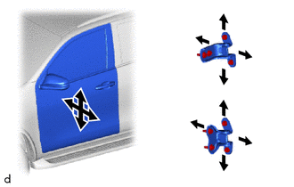
Check that the clearance measurements of areas A to J are within the standard ranges.
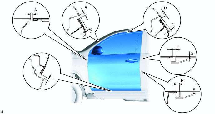
Standard Clearance A 2.8 to 5.8 mm (0.110 to 0.228 in.) B 3.2 to 6.2 mm (0.126 to 0.244 in.) C 2.2 to 5.2 mm (0.087 to 0.205 in.) D 3.2 to 6.2 mm (0.126 to 0.244 in.) E 2.5 to 5.5 mm (0.098 to 0.217 in.) F 3.2 to 6.2 mm (0.126 to 0.244 in.) G -1.5 to 1.5 mm (-0.059 to 0.059 in.) H 3.2 to 6.2 mm (0.126 to 0.244 in.) I -1.5 to 1.5 mm (-0.059 to 0.059 in.) J 4.2 to 7.2 mm (0.165 to 0.283 in.)
-
-
ADJUST FRONT DOOR PANEL SUB-ASSEMBLY LH
-
Using SST, loosen the hinge bolts on the body and adjust the door position.
- SST
- 09812-00010
-
Tighten the hinge bolts on the body after the adjustment.
- Torque:
- 21 N*m { 214 kgf*cm, 15 ft.*lbf }
-
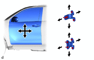
Loosen the hinge bolts on the door and adjust the door position.
-
Tighten the hinge bolts on the door after the adjustment.
- Torque:
- 26 N*m { 265 kgf*cm, 19 ft.*lbf }
-
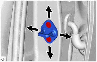
Using a T40 "TORX" socket wrench, adjust the striker position by slightly loosening the striker mounting screws and hitting the striker with a plastic-faced hammer.
-
Using a T40 "TORX" socket wrench, tighten the striker mounting screws after the adjustment.
- Torque:
- 23 N*m { 235 kgf*cm, 17 ft.*lbf }
-
-
CONNECT CABLE TO NEGATIVE BATTERY TERMINAL
Note
When disconnecting the cable, some systems need to be initialized after the cable is reconnected.
-
CHECK SRS WARNING LIGHT