POWER BACK DOOR SYSTEM Power Back Door Warning System does not Operate
DESCRIPTION
When the power back door warning system does not operate, one of the following may be malfunctioning: 1) wireless door lock control system, 2) power back door warning buzzer circuit or 3) multiplex network door ECU.
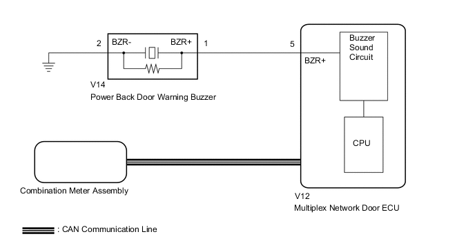
WIRING DIAGRAM
CAUTION / NOTICE / HINT
Note
-
If the replacement, removal and installation of the multiplex network door ECU or disconnection of the connectors of the multiplex network door ECU has been performed, initialize the power back door system.
-
The power back door warning function can be customized. Make sure the function is ON.
PROCEDURE
-
CHECK OPERATION
-
Check power back door system operation.
Result Result Proceed to Hazard warning light does not come on A Power back door warning buzzer does not operate B
B 
PERFORM ACTIVE TEST USING GTS Click here
A 
-
-
CHECK WIRELESS DOOR LOCK CONTROL SYSTEM (HAZARD ANSWER-BACK FUNCTION)
-
Check wireless door lock operation.
OK Hazard answer-back function operates normally. Result Proceed to OK NG
OK 
REPLACE MULTIPLEX NETWORK DOOR ECU Click here
NG
GO TO WIRELESS DOOR LOCK CONTROL SYSTEM Click here
-
-
PERFORM ACTIVE TEST USING GTS
-
Check the Data List for proper functioning of the wireless door lock buzzer.
Body Electrical > Back Door > Active TestTester Display Measurement Item Control Range Diagnostic Note PBD Buzzer Power back door warning buzzer sound ON or OFF -
Body Electrical > Back Door > Active TestTester Display PBD Buzzer OK Power back door warning buzzer sounds. Result Proceed to OK NG
OK
REPLACE MULTIPLEX NETWORK DOOR ECU Click here
NG
-
-
CHECK HARNESS AND CONNECTOR (POWER BACK DOOR WARNING BUZZER - MULTIPLEX NETWORK DOOR ECU AND BODY GROUND)
-
Disconnect the V14 power back door warning buzzer connector.
-
Disconnect the V12 multiplex network door ECU connector.
-
Measure the resistance according to the value(s) in the table below.
Standard Resistance Tester Connection Condition Specified Condition V14-1 (BZR+) - V12-5 (BZR+) Always Below 1 Ω V14-2 (BZR-) - Body ground Always Below 1 Ω V14-1 (BZR+) or V12-5 (BZR+) - Body ground Always 10 kΩ or higher Result Proceed to OK NG
NG
REPAIR OR REPLACE HARNESS OR CONNECTOR
OK
-
-
REPLACE POWER BACK DOOR WARNING BUZZER
-
Temporarily replace the power back door warning buzzer with a new or normally functioning one.
Result Proceed to NEXT
NEXT
-
-
CHECK POWER BACK DOOR SYSTEM
-
Check that the power back door warning buzzer operates normally.
OK Power back door warning buzzer sounds. Result Proceed to OK NG
OK
END (POWER BACK DOOR WARNING BUZZER WAS DEFECTIVE)
NG
REPLACE MULTIPLEX NETWORK DOOR ECU Click here
-