BACK DOOR CLOSER SYSTEM, Diagnostic DTC:B2251
| DTC Code | DTC Name |
|---|---|
| B2251 | Back Door Closer Switch Malfunction |
DESCRIPTION
The multiplex network door ECU receives signals from the half latch switch, initial switch, pawl switch and back door courtesy switch, which are built into the back door lock assembly. Based on these switch signals, the latch position of the back door lock assembly is determined.
| DTC No. | Detection Item | DTC Detection Condition | Trouble Area |
|---|---|---|---|
| B2251 | Back Door Closer Switch Malfunction | While the back door closer is operating, a malfunction is detected in position information from the back door courtesy switch within a specified amount of time. |
|
WIRING DIAGRAM
Figure 1. w/ Power Back Door System
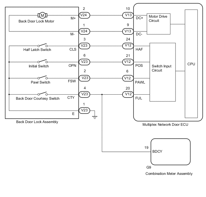
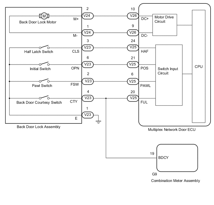
Figure 2. w/o Power Back Door System
CAUTION / NOTICE / HINT
Note
-
If the replacement, removal and installation of the multiplex network door ECU or disconnection of the connectors of the multiplex network door ECU has been performed, initialize the power back door system*.
-
The back door closer system uses the meter / gauge system function. First, confirm that there is no malfunction in the meter / gauge system. Refer to the How to Proceed with Troubleshooting procedure.
-
*: w/ Power Back Door System
PROCEDURE
-
READ VALUE USING GTS
-
Read the Data List according to the display on the GTS.
Body Electrical > Back Door > Data ListTester Display Measurement Item Range Normal Condition Diagnostic Note Courtesy SW Back door courtesy switch signal ON or OFF ON: Back door open
OFF: Back door closed
*: Refer to "CONSTRUCTION AND OPERATION" *: Refer to "CONSTRUCTION AND OPERATION"
Body Electrical > Back Door > Data ListTester Display Courtesy SW OK The display is as specified in the normal condition column. Result Proceed to OK NG
OK 
REPLACE MULTIPLEX NETWORK DOOR ECU Click here
NG 
-
-
INSPECT BACK DOOR LOCK ASSEMBLY
-
Remove the back door lock assembly.
-
Inspect the back door lock assembly.
Result Proceed to OK NG
NG
REPLACE BACK DOOR LOCK ASSEMBLY Click here
OK
-
-
CHECK HARNESS AND CONNECTOR (BACK DOOR LOCK ASSEMBLY - MULTIPLEX NETWORK DOOR ECU AND BODY GROUND)
-
w/ Power Back Door System:
-
Disconnect the V23 back door lock assembly connector.
-
Disconnect the V12 multiplex network door ECU connector.
-
Disconnect the G9 combination meter assembly connector.
-
Measure the resistance according to the value(s) in the table below.
Standard Resistance Tester Connection Condition Specified Condition V23-4 (CTY) - V12-20 (FUL) Always Below 1 Ω V23-1 (E) - Body ground Always Below 1 Ω V23-4 (CTY) or V12-20 (FUL) - Body ground Always 10 kΩ or higher
-
-
w/o Power Back Door System:
-
Disconnect the V23 back door lock assembly connector.
-
Disconnect the V25 multiplex network door ECU connector.
-
Disconnect the G9 combination meter assembly connector.
-
Measure the resistance according to the value(s) in the table below.
Standard Resistance Tester Connection Condition Specified Condition V23-4 (CTY) - V25-20 (FUL) Always Below 1 Ω V23-1 (E) - Body ground Always Below 1 Ω V23-4 (CTY) or V25-20 (FUL) - Body ground Always 10 kΩ or higher
Result Proceed to OK NG -
OK
REPLACE MULTIPLEX NETWORK DOOR ECU Click here
NG
REPAIR OR REPLACE HARNESS OR CONNECTOR
-