BACK DOOR CLOSER SYSTEM TERMINALS OF ECU
-
CHECK MULTIPLEX NETWORK DOOR ECU
Note
If the replacement, removal and installation of the multiplex network door ECU or disconnection of the connectors of the multiplex network door ECU has been performed, initialize the power back door system.
-
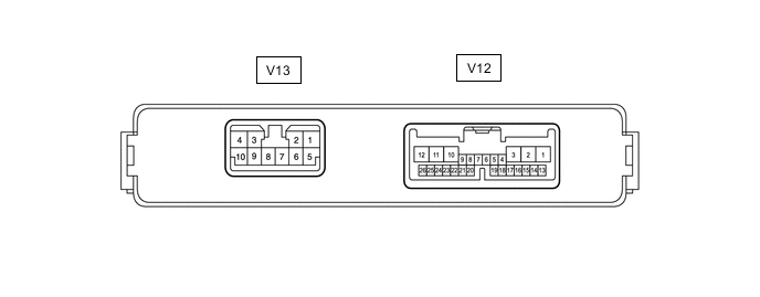
Disconnect the V12 and V13 multiplex network door ECU connectors.
-
Measure the voltage and resistance according to the value(s) in the table below.
Tech Tips
Measure the values on the wire harness side with the connector disconnected.
Terminal No. (Symbol) Wiring Color Terminal Description Condition Specified Condition V12-1 (ECUB) - Body ground W - Body ground Battery power supply Always 11 to 14 V V12-7 (IG) - Body ground V - Body ground IG power supply Engine switch on (IG) 11 to 14 V Engine switch off Below 1 V V13-8 (B) - Body ground G - Body ground Battery power supply Always 11 to 14 V V13-7 (GND) - Body ground W-B - Body ground Body ground Always Below 1 Ω -
Reconnect the V12 and V13 multiplex network door ECU connectors.
-
Measure the voltage and waveform according to the value(s) in the table below.
Terminal No. (Symbol) Wiring Color Terminal Description Condition Specified Condition V13-10 (DC+) - V13-9 (DC-) B - R Back door lock assembly (back door lock motor) circuit Back door lock motor operating 11 to 14 V Back door lock motor not operating Below 1 V V12-20 (FUL) - Body ground W - Body ground Back door lock assembly (back door courtesy switch) signal circuit Back door closed → open Pulse generation → Below 1 V V12-24 (HAF) - Body ground G - Body ground Back door lock assembly (half latch switch) signal circuit Back door closed → fully open 11 to 14 V → Below 1 V V12-21 (POS) - Body ground GR - Body ground Back door lock assembly (initial switch) signal circuit Back door open → Back door closer operates → Back door closed Below 1 V → 11 to 14 V → Below 1 V
-
-
CHECK CERTIFICATION ECU (SMART KEY ECU ASSEMBLY)
-
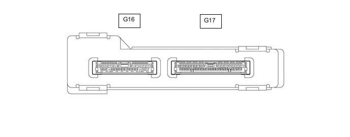
Disconnect the G16 certification ECU (smart key ECU assembly) connector.
-
Measure the voltage and resistance according to the value(s) in the table below.
Tech Tips
Measure the values on the wire harness side with the connector disconnected.
Terminal No. (Symbol) Wiring Color Terminal Description Condition Specified Condition G16-1 (+B) - Body ground P - Body ground Battery power supply Always 11 to 14 V G16-10 (E) - Body ground BR - Body ground Body ground Always Below 1 Ω -
Reconnect the G16 certification ECU (smart key ECU assembly) connector.
-
Measure the voltage according to the value(s) in the table below.
Terminal No. (Symbol) Wiring Color Terminal Description Condition Specified Condition G16-14 (TSW5) - G16-10 (E) V - BR Back door opener switch assembly signal Back door opener switch assembly (open switch) off → on 4.5 V or higher → Below 1.5 V
-