WINDSHIELD DEICER SWITCH INSPECTION
PROCEDURE
-
INSPECT AIR CONDITIONING CONTROL ASSEMBLY (for Manual Air Conditioning System)
-
Check the switch function.
-
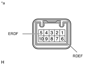
*a Component without harness connected
(Air Conditioning Control Assembly (Window Deicer Switch))
Measure the resistance when the switch is operated according to the value(s) in the table below.
Standard Resistance Tester Connection Switch Condition Specified Condition 6 (RDEF) - 5 (ERDF) Push (ON) Below 1 Ω Not push (OFF) 10 kΩ or higher If the result is not as specified, replace the air conditioning control assembly (window deicer switch).
-
-
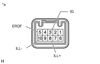
*a Component without harness connected
(Air Conditioning Control Assembly (Window Deicer Switch))
Check that the LED illuminates.
-
Apply battery voltage to the air conditioning control assembly (window deicer switch) and check that the LED illuminates.
OK Battery Connection Specified Condition Battery positive (+) → 8 (ILL+)
Battery negative (-) → 10 (ILL-)
LED illuminates If the result is not as specified, replace the air conditioning control assembly (window deicer switch).
-
Apply battery voltage to the air conditioning control assembly (window deicer switch) and check that the indicator.
Standard Resistance Battery Connection Condition Specified Condition Battery positive (+) → 3 (IG)
Battery negative (-) → 5 (ERDF)
Push (ON) Indicator illuminates Not push (OFF) Indicator not illuminates If the result is not as specified, replace the air conditioning control assembly (window deicer switch).
-
-