BACK DOOR CLOSER SYSTEM Back Door Closer does not Operate
DESCRIPTION
When the back door closer does not operate, one of the following may be the cause: 1) improper fit of the back door, or a foreign object is stuck in the back door, 2) a malfunction in the multiplex network door ECU power source circuit, 3) a malfunction in the back door lock assembly circuit, or 4) a malfunction in the multiplex network door ECU.
WIRING DIAGRAM
Figure 1. w/ Power Back Door System
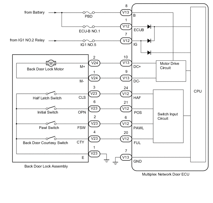
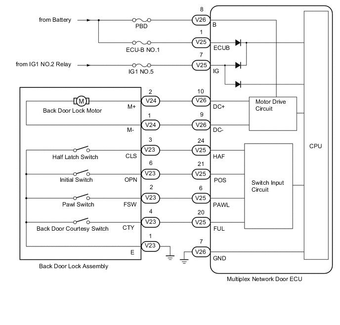
Figure 2. w/o Power Back Door System
CAUTION / NOTICE / HINT
Note
-
Inspect fuses for circuits related to this system before performing the following inspection procedure.
-
If the replacement, removal and installation of the multiplex network door ECU or disconnection of the connectors of the multiplex network door ECU has been performed, initialize the power back door system*.
-
*: w/ Power Back Door System
PROCEDURE
-
CHECK FOR DTC
-
Check for DTCs.
Body Electrical > Back Door > Trouble CodesResult Result Proceed to DTC is not output A DTC B2250 is output B DTC B2251 is output C
B 
GO TO DTC B2250 Click here
C
GO TO DTC B2251 Click here
A 
-
-
CHECK BACK DOOR LOCK FUNCTION
-
Turn the power back door main switch so that it is not pushed.
-
Check if the back door can be fully closed by hand.
Result Result Proceed to The back door can be closed normally A The back door cannot be closed normally B
B
IMPROPER FIT OF BACK DOOR, OR A FOREIGN OBJECT IS STUCK IN BACK DOOR
A
-
-
CHECK HARNESS AND CONNECTOR (MULTIPLEX NETWORK DOOR ECU - BATTERY AND BODY GROUND)
-
w/ Power Back Door System:
-
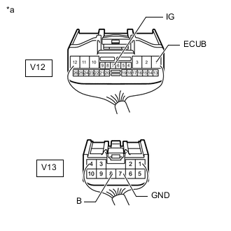
*a Rear view of wire harness connector
(to Multiplex Network Door ECU)
Disconnect the multiplex network door ECU connectors.
-
Disconnect the multiplex network door ECU connectors.
-
Measure the resistance according to the value(s) in the table below.
Standard Resistance Tester Connection Condition Specified Condition V13-7 (GND) - Body ground Always Below 1 Ω -
Measure the voltage according to the value(s) in the table below.
Standard Voltage Tester Connection Condition Specified Condition V12-1 (ECUB) - Body ground Always 11 to 14 V V13-8 (B) - Body ground Always 11 to 14 V V12-7 (IG) - Body ground Engine switch on (IG) 11 to 14 V Engine switch off Below 1 V
-
-
w/o Power Back Door System:
-
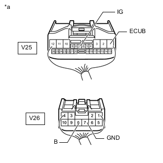
*a Rear view of wire harness connector
(to Multiplex Network Door ECU)
Disconnect the multiplex network door ECU connectors.
-
Disconnect the multiplex network door ECU connectors.
-
Measure the resistance according to the value(s) in the table below.
Standard Resistance Tester Connection Condition Specified Condition V26-7 (GND) - Body ground Always Below 1 Ω -
Measure the voltage according to the value(s) in the table below.
Standard Voltage Tester Connection Condition Specified Condition V25-1 (ECUB) - Body ground Always 11 to 14 V V26-8 (B) - Body ground Always 11 to 14 V V25-7 (IG) - Body ground Engine switch on (IG) 11 to 14 V Engine switch off Below 1 V
Result Proceed to OK NG -
NG
REPAIR OR REPLACE HARNESS OR CONNECTOR
OK
-
-
INSPECT BACK DOOR LOCK ASSEMBLY
-
Remove the back door lock assembly.
-
Inspect the back door lock assembly.
Result Proceed to OK NG
NG
REPLACE BACK DOOR LOCK ASSEMBLY Click here
OK
-
-
CHECK HARNESS AND CONNECTOR (BACK DOOR LOCK ASSEMBLY - MULTIPLEX NETWORK DOOR ECU AND BODY GROUND)
-
w/ Power Back Door System:
-
Disconnect the V23 and V24 back door lock assembly connectors.
-
Disconnect the V12 and V13 multiplex network door ECU connectors.
-
Disconnect the G9 combination meter assembly connector.
-
Measure the resistance according to the value(s) in the table below.
Standard Resistance Tester Connection Condition Specified Condition V24-2 (M+) - V13-10 (DC+) Always Below 1 Ω V24-1 (M-) - V13-9 (DC-) Always Below 1 Ω V23-4 (CTY) - V12-20 (FUL) Always Below 1 Ω V23-2 (FSW) - V12-6 (PAWL) Always Below 1 Ω V23-3 (CLS) - V12-24 (HAF) Always Below 1 Ω V23-6 (OPN) - V12-21 (POS) Always Below 1 Ω V23-1 (E) - Body ground Always Below 1 Ω V23-2 (M+) or V13-10 (DC+) - Body ground Always 10 kΩ or higher V23-1 (M-) or V13-9 (DC-) - Body ground Always 10 kΩ or higher V23-2 (FSW) or V12-6 (PAWL) - Body ground Always 10 kΩ or higher V23-4 (CTY) or V12-20 (FUL) - Body ground Always 10 kΩ or higher V23-3 (CLS) or V12-24 (HAF) - Body ground Always 10 kΩ or higher V23-6 (OPN) or V12-21 (POS) - Body ground Always 10 kΩ or higher
-
-
w/o Power Back Door System:
-
Disconnect the V23 and V24 back door lock assembly connectors.
-
Disconnect the V25 and V26 multiplex network door ECU connectors.
-
Disconnect the G9 combination meter assembly connector.
-
Measure the resistance according to the value(s) in the table below.
Standard Resistance Tester Connection Condition Specified Condition V24-2 (M+) - V13-10 (DC+) Always Below 1 Ω V24-1 (M-) - V13-9 (DC-) Always Below 1 Ω V23-4 (CTY) - V12-20 (FUL) Always Below 1 Ω V23-2 (FSW) - V12-6 (PAWL) Always Below 1 Ω V23-3 (CLS) - V12-24 (HAF) Always Below 1 Ω V23-6 (OPN) - V12-21 (POS) Always Below 1 Ω V23-1 (E) - Body ground Always Below 1 Ω V23-2 (M+) or V13-10 (DC+) - Body ground Always 10 kΩ or higher V23-1 (M-) or V13-9 (DC-) - Body ground Always 10 kΩ or higher V23-2 (FSW) or V12-6 (PAWL) - Body ground Always 10 kΩ or higher V23-4 (CTY) or V12-20 (FUL) - Body ground Always 10 kΩ or higher V23-3 (CLS) or V12-24 (HAF) - Body ground Always 10 kΩ or higher V23-6 (OPN) or V12-21 (POS) - Body ground Always 10 kΩ or higher
Result Proceed to OK NG -
OK
REPLACE MULTIPLEX NETWORK DOOR ECU Click here
NG
REPAIR OR REPLACE HARNESS OR CONNECTOR
-