WINDSHIELD DEICER SYSTEM TERMINALS OF ECU
-
CHECK AIR CONDITIONING AMPLIFIER ASSEMBLY (for Automatic Air Conditioning System)
-
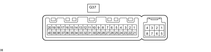
Disconnect the G37 air conditioning amplifier assembly connector.
-
Measure the voltage and resistance according to the value(s) in the table below.
Tester Connection Wiring Color Terminal Description Condition Specified Condition G37-1 (IG+) - Body ground G - Body ground Power source (IG) Ignition switch ON 11 to 14 V Ignition switch off Below 1 V G37-21 (B) - Body ground W - Body ground Battery power supply Always 11 to 14 V G37-14 (GND) - Body ground W-B - Body ground Ground Always Below 1 Ω -
Reconnect the G37 air conditioning amplifier assembly connector.
-
Measure the voltage according to the value(s) in the table below.
Tester Connection Wiring Color Terminal Description Condition Specified Condition G37-18 (FDEF) - Body ground P - Body ground Deicer signal Ignition switch ON, defogger switch (deicer switch) off Below 1 V Ignition switch ON, defogger switch (deicer switch) on 11 to 14 V
-