POWER WINDOW CONTROL SYSTEM TERMINALS OF ECU
-
CHECK POWER WINDOW REGULATOR MASTER SWITCH ASSEMBLY (w/ Smart Entry and Start System)
-
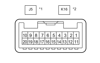
*1 for RHD *2 for LHD Disconnect the J5*1 or K16*2 power window regulator master switch assembly connector.
-
*1: for RHD
-
*2: for LHD
-
-
Measure the voltage and resistance according to the value(s) in the table below.
Tech Tips
Measure the values on the wire harness side with the connector disconnected.
for RHD Tester Connection Wiring Color Terminal Description Condition Specified Condition J5-11 (B) - J5-12 (GND) Y - W-B Power supply Always 11 to 14 V J5-12 (GND) - Body ground W-B - Body ground Ground Always Below 1 Ω for LHD Tester Connection Wiring Color Terminal Description Condition Specified Condition K16-11 (B) - K16-12 (GND) Y - W Power supply Always 11 to 14 V K16-12 (GND) - Body ground W - Body ground Ground Always Below 1 Ω -
Reconnect the J5*1 or K16*2 power window regulator master switch assembly connector.
-
*1: for RHD
-
*2: for LHD
-
-
Measure the voltage and waveform according to the value(s) in the table below.
for RHD Tester Connection Wiring Color Terminal Description Condition Specified Condition J5-15 (DOWN) - J5-12 (GND) P - W-B Driver door power window motor DOWN output Ignition switch ON, driver door power window regulator switch not pushed or pulled 11 to 14 V Ignition switch ON, driver door power window moving, driver door power window regulator switch pushed halfway down (Manual operation) Below 1 V J5-20 (UP) - J5-12 (GND) B - W-B Driver door power window motor UP output Ignition switch ON, driver door power window regulator switch not pushed or pulled 11 to 14 V Ignition switch ON, driver door power window moving, driver door power window regulator switch pulled halfway up (Manual operation) Below 1 V LIN communication signal Ignition switch ON Pulse generation for LHD Tester Connection Wiring Color Terminal Description Condition Specified Condition K16-15 (DOWN) - K16-12 (GND) P - W Driver door power window motor DOWN output Ignition switch ON, driver door power window regulator switch not pushed or pulled 11 to 14 V Ignition switch ON, driver door power window moving, driver door power window regulator switch pushed halfway down (Manual operation) Below 1 V K16-20 (UP) - K16-12 (GND) B - W Driver door power window motor UP output Ignition switch ON, driver door power window regulator switch not pushed or pulled 11 to 14 V Ignition switch ON, driver door power window moving, driver door power window regulator switch pulled halfway up (Manual operation) Below 1 V LIN communication signal Ignition switch ON Pulse generation
-
-
CHECK POWER WINDOW REGULATOR MASTER SWITCH ASSEMBLY (w/o Smart Entry and Start System)
-
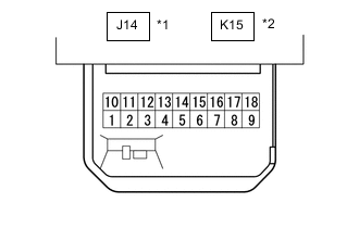
*1 for RHD *2 for LHD Disconnect the J14*1 or K15*2 power window regulator master switch assembly connector.
-
*1: for RHD
-
*2: for LHD
-
-
Measure the voltage and resistance according to the value(s) in the table below.
Tech Tips
Measure the values on the wire harness side with the connector disconnected.
for RHD Tester Connection Wiring Color Terminal Description Condition Specified Condition J14-7 (B) - J14-9 (E) LA-GR - W-B IG power supply Ignition switch ON 11 to 14 V Ignition switch off Below 1 V J14-9 (E) - Body ground W-B - Body ground Ground Always Below 1 Ω for LHD Tester Connection Wiring Color Terminal Description Condition Specified Condition K15-7 (B) - K15-1 (E) LA-GR - W-B IG power supply Ignition switch ON 11 to 14 V Ignition switch off Below 1 V K15-1 (E) - Body ground W-B - Body ground Ground Always Below 1 Ω -
Reconnect the J14*1 or K15*2 power window regulator master switch assembly connector.
-
*1: for RHD
-
*2: for LHD
-
-
Measure the voltage according to the value(s) in the table below.
for RHD Tester Connection Wiring Color Terminal Description Condition Specified Condition J14-3 (U) - J14-9 (E) B - W-B Driver door power window motor up output Ignition switch ON, driver door power window switch not pushed or pulled 11 to 14 V Ignition switch ON, driver door power window switch pulled halfway up (Manual operation) Below 1 V J14-4 (A) - J14-9 (E) SB - W-B Driver door power window motor auto up output Ignition switch ON, driver door power window fully open 11 to 14 V Ignition switch ON, driver door power window switch fully pulled up (AUTO operation) Below 1 V Ignition switch ON, driver door power window fully closed 11 to 14 V Driver door power window motor auto down output Ignition switch ON, driver door power window fully closed 11 to 14 V Ignition switch ON, driver door power window switch fully pushed down (AUTO operation) Below 1 V Ignition switch ON, driver door power window fully open 11 to 14 V J14-6 (D) - J14-9 (E) P - W-B Driver door power window motor down output Ignition switch ON, driver door power window switch not pushed or pulled 11 to 14 V Ignition switch ON, driver door power window switch pushed halfway down (Manual operation) Below 1 V J14-10 (U) - J14-9 (E) LA-R - W-B Front passenger door power window motor up output Ignition switch ON, front passenger door power window switch not pushed or pulled 11 to 14 V Ignition switch ON, front passenger door power window switch pulled up (Manual operation) Below 1 V J14-18 (D) - J14-9 (E) LA-G - W-B Front passenger door power window motor down output Ignition switch ON, front passenger door power window switch not pushed or pulled 11 to 14 V Ignition switch ON, front passenger door power window switch pushed down (Manual operation) Below 1 V J14-12 (U) - J14-9 (E) LA-Y - W-B Rear door LH power window motor up output Ignition switch ON, rear LH door power window switch not pushed or pulled 11 to 14 V Ignition switch ON, rear LH door power window switch pulled up (Manual operation) Below 1 V J14-13 (D) - J14-9 (E) LA-P - W-B Rear door LH power window motor down output Ignition switch ON, rear LH door power window switch not pushed or pulled 11 to 14 V Ignition switch ON, rear LH door power window switch pushed down (Manual operation) Below 1 V J14-15 (U) - J14-9 (E) LA-B - W-B Rear door RH power window motor up output Ignition switch ON, rear RH door power window switch not pushed or pulled 11 to 14 V Ignition switch ON, rear RH door power window switch pulled up (Manual operation) Below 1 V J14-16 (D) - J14-9 (E) LA-V - W-B Rear door RH power window motor down output Ignition switch ON, rear RH door power window switch not pushed or pulled 11 to 14 V Ignition switch ON, rear RH door power window switch pushed down (Manual operation) Below 1 V for LHD Tester Connection Wiring Color Terminal Description Condition Specified Condition K15-6 (U) - K15-1 (E) B - W-B Driver door power window motor up output Ignition switch ON, driver door power window switch not pushed or pulled 11 to 14 V Ignition switch ON, driver door power window switch pulled halfway up (Manual operation) Below 1 V K15-4 (A) - K15-1 (E) SB - W-B Driver door power window motor auto up output Ignition switch ON, driver door power window fully open 11 to 14 V Ignition switch ON, driver door power window switch fully pulled up (AUTO operation) Below 1 V Ignition switch ON, driver door power window fully closed 11 to 14 V Driver door power window motor auto down output Ignition switch ON, driver door power window fully closed 11 to 14 V Ignition switch ON, driver door power window switch fully pushed down (AUTO operation) Below 1 V Ignition switch ON, driver door power window fully open 11 to 14 V K15-3 (D) - K15-1 (E) P - W-B Driver door power window motor down output Ignition switch ON, driver door power window switch not pushed or pulled 11 to 14 V Ignition switch ON, driver door power window switch pushed halfway down (Manual operation) Below 1 V K15-10 (U) - K15-1 (E) LA-R - W-B Front passenger door power window motor up output Ignition switch ON, front passenger door power window switch not pushed or pulled 11 to 14 V Ignition switch ON, front passenger door power window switch pulled up (Manual operation) Below 1 V K15-18 (D) - K15-1 (E) LA-G - W-B Front passenger door power window motor down output Ignition switch ON, front passenger door power window switch not pushed or pulled 11 to 14 V Ignition switch ON, front passenger door power window switch pushed down (Manual operation) Below 1 V K15-12 (U) - K15-1 (E) LA-Y - W-B Rear door LH power window motor up output Ignition switch ON, rear LH door power window switch not pushed or pulled 11 to 14 V Ignition switch ON, rear LH door power window switch pulled up (Manual operation) Below 1 V K15-13 (D) - K15-1 (E) LA-P - W-B Rear door LH power window motor down output Ignition switch ON, rear LH door power window switch not pushed or pulled 11 to 14 V Ignition switch ON, rear LH door power window switch pushed down (Manual operation) Below 1 V K15-15 (U) - K15-1 (E) LA-B - W-B Rear door RH power window motor up output Ignition switch ON, rear RH door power window switch not pushed or pulled 11 to 14 V Ignition switch ON, rear RH door power window switch pulled up (Manual operation) Below 1 V K15-16 (D) - K15-1 (E) LA-V - W-B Rear door RH power window motor down output Ignition switch ON, rear RH door power window switch not pushed or pulled 11 to 14 V Ignition switch ON, rear RH door power window switch pushed down (Manual operation) Below 1 V
-
-
CHECK FRONT POWER WINDOW REGULATOR MOTOR ASSEMBLY RH (w/ Smart Entry and Start System)
-
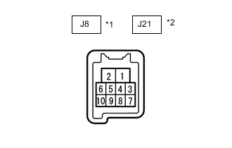
*1 for RHD *2 for LHD Disconnect the J8*1 or J21*2 front power window regulator motor assembly RH connector.
-
*1: for RHD
-
*2: for LHD
-
-
Measure the voltage and resistance according to the value(s) in the table below.
Tech Tips
Measure the values on the wire harness side with the connector disconnected.
for RHD Tester Connection Wiring Color Terminal Description Condition Specified Condition J8-1 (GND) - Body ground LA-W - Body ground Ground Always Below 1 Ω J8-2 (B) - Body ground LA-GR - Body ground Power supply Always 11 to 14 V for LHD Tester Connection Wiring Color Terminal Description Condition Specified Condition J21-1 (GND) - Body ground W-B - Body ground Ground Always Below 1 Ω J21-2 (B) - Body ground GR - Body ground Power supply Always 11 to 14 V -
Reconnect the J8*1 or J21*2 front power window regulator motor assembly RH connector.
-
*1: for RHD
-
*2: for LHD
-
-
Measure the voltage according to the value(s) in the table below.
for RHD Tester Connection Wiring Color Terminal Description Condition Specified Condition J8-7 (DOWN) - J8-1 (GND) P - LA-W Power window motor DOWN input Ignition switch ON, power window master switch (driver door power window regulator switch) not pushed or pulled 11 to 14 V Ignition switch ON, driver door power window moving, power window master switch (driver door power window regulator switch) pushed halfway down (Manual operation) Below 1 V Ignition switch ON, driver door power window fully closed 11 to 14 V Ignition switch ON, driver door power window moving, power window master switch (driver door power window regulator switch) fully pushed down (Auto operation) Below 1 V Ignition switch ON, driver door power window fully open 11 to 14 V J8-10 (UP) - J8-1 (GND) B - LA-W Power window motor UP input Ignition switch ON, power window master switch (driver door power window regulator switch) not pushed or pulled 11 to 14 V Ignition switch ON, driver door power window moving, power window master switch (driver door power window regulator switch) pulled halfway up (Manual operation) Below 1 V Ignition switch ON, power window master switch (driver door power window regulator switch) fully open 11 to 14 V Ignition switch ON, driver door power window moving, power window master switch (driver door power window regulator switch) fully pulled up (Auto operation) Below 1 V Ignition switch ON, driver door power window fully closed 11 to 14 V for LHD Tester Connection Wiring Color Terminal Description Condition Specified Condition J21-4 (AUTO) - J21-1 (GND) L - W-B Power window motor AUTO UP input Ignition switch ON, front passenger door power window fully open 11 to 14 V Ignition switch ON, front passenger door power window moving, power window regulator switch assembly fully pulled up (Auto operation) Below 1 V Ignition switch ON, front passenger door power window fully closed 11 to 14 V Power window motor AUTO DOWN input Ignition switch ON, front passenger door power window fully closed 11 to 14 V Ignition switch ON, front passenger door power window moving, power window regulator switch assembly fully pushed down (Auto operation) Below 1 V Ignition switch ON, front passenger door power window fully open 11 to 14 V J21-7 (DOWN) - J21-1 (GND) P - W-B Power window motor DOWN input Ignition switch ON, power window master switch (driver door power window regulator switch) not pushed or pulled 11 to 14 V Ignition switch ON, driver door power window moving, power window master switch (driver door power window regulator switch) pushed halfway down (Manual operation) Below 1 V Ignition switch ON, driver door power window fully closed 11 to 14 V Ignition switch ON, driver door power window moving, power window master switch (driver door power window regulator switch) fully pushed down (Auto operation) Below 1 V Ignition switch ON, driver door power window fully open 11 to 14 V J21-10 (UP) - J21-1 (GND) B - W-B Power window motor UP input Ignition switch ON, power window master switch (driver door power window regulator switch) not pushed or pulled 11 to 14 V Ignition switch ON, driver door power window moving, power window master switch (driver door power window regulator switch) pulled halfway up (Manual operation) Below 1 V Ignition switch ON, power window master switch (driver door power window regulator switch) fully open 11 to 14 V Ignition switch ON, driver door power window moving, power window master switch (driver door power window regulator switch) fully pulled up (Auto operation) Below 1 V Ignition switch ON, driver door power window fully closed 11 to 14 V
-
-
CHECK FRONT POWER WINDOW REGULATOR MOTOR ASSEMBLY RH (w/o Smart Entry and Start System for RHD)
-
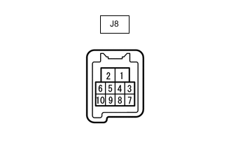
Disconnect the J8 front power window regulator motor assembly RH connector.
-
Measure the voltage and resistance according to the value(s) in the table below.
Tech Tips
Measure the values on the wire harness side with the connector disconnected.
Tester Connection Wiring Color Terminal Description Condition Specified Condition J8-1 (GND) - Body ground LA-W - Body ground Ground Always Below 1 Ω J8-2 (B) - Body ground LA-GR - Body ground Power supply Always 11 to 14 V -
Reconnect the J8 front power window regulator motor assembly RH connector.
-
Measure the voltage according to the value(s) in the table below.
Tester Connection Wiring Color Terminal Description Condition Specified Condition J8-7 (DOWN) - J8-1 (GND) P - LA-W Power window motor DOWN input Ignition switch ON, power window master switch (driver door power window regulator switch) not pushed or pulled 11 to 14 V Ignition switch ON, driver door power window moving, power window master switch (driver door power window regulator switch) pushed halfway down (Manual operation) Below 1 V Ignition switch ON, driver door power window fully closed 11 to 14 V Ignition switch ON, driver door power window moving, power window master switch (driver door power window regulator switch) fully pushed down (Auto operation) Below 1 V Ignition switch ON, driver door power window fully open 11 to 14 V J8-10 (UP) - J8-1 (GND) B - LA-W Power window motor UP input Ignition switch ON, power window master switch (driver door power window regulator switch) not pushed or pulled 11 to 14 V Ignition switch ON, driver door power window moving, power window master switch (driver door power window regulator switch) pulled halfway up (Manual operation) Below 1 V Ignition switch ON, power window master switch (driver door power window regulator switch) fully open 11 to 14 V Ignition switch ON, driver door power window moving, power window master switch (driver door power window regulator switch) fully pulled up (Auto operation) Below 1 V Ignition switch ON, driver door power window fully closed 11 to 14 V
-
-
CHECK FRONT POWER WINDOW REGULATOR MOTOR ASSEMBLY LH (w/ Smart Entry and Start System)
-
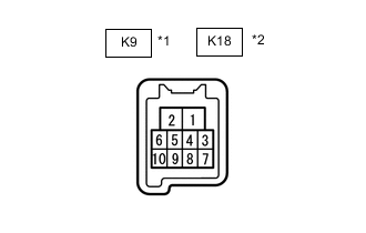
*1 for RHD *2 for LHD Disconnect the K9*1 or K18*2 front power window regulator motor assembly LH connector.
-
*1: for RHD
-
*2: for LHD
-
-
Measure the voltage and resistance according to the value(s) in the table below.
Tech Tips
Measure the values on the wire harness side with the connector disconnected.
for RHD Tester Connection Wiring Color Terminal Description Condition Specified Condition K9-1 (GND) - Body ground W-B - Body ground Ground Always Below 1 Ω K9-2 (B) - Body ground GR - Body ground Power supply Always 11 to 14 V for LHD Tester Connection Wiring Color Terminal Description Condition Specified Condition K18-1 (GND) - Body ground LA-W - Body ground Ground Always Below 1 Ω K18-2 (B) - Body ground LA-GR - Body ground Power supply Always 11 to 14 V -
Reconnect the K9*1 or K18*2 front power window regulator motor assembly LH connector.
-
*1: for RHD
-
*2: for LHD
-
-
Measure the voltage according to the value(s) in the table below.
for RHD Tester Connection Wiring Color Terminal Description Condition Specified Condition K9-4 (AUTO) - K9-1 (GND) L - W-B Power window motor AUTO UP input Ignition switch ON, front passenger door power window fully open 11 to 14 V Ignition switch ON, front passenger door power window moving, power window regulator switch assembly fully pulled up (Auto operation) Below 1 V Ignition switch ON, front passenger door power window fully closed 11 to 14 V Power window motor AUTO DOWN input Ignition switch ON, front passenger door power window fully closed 11 to 14 V Ignition switch ON, front passenger door power window moving, power window regulator switch assembly fully pushed down (Auto operation) Below 1 V Ignition switch ON, front passenger door power window fully open 11 to 14 V K9-7 (DOWN) - K9-1 (GND) P - W-B Power window motor DOWN input Ignition switch ON, power window regulator switch assembly not pushed or pulled 11 to 14 V Ignition switch ON, front passenger door power window moving, power window regulator switch assembly pushed halfway down (Manual operation) Below 1 V Ignition switch ON, front passenger door power window fully closed 11 to 14 V Ignition switch ON, front passenger door power window moving, power window regulator switch assembly fully pushed down (Auto operation) Below 1 V Ignition switch ON, front passenger door power window fully open 11 to 14 V K9-10 (UP) - K9-1 (GND) B - W-B Power window motor UP input Ignition switch ON, power window regulator switch assembly not pushed or pulled 11 to 14 V Ignition switch ON, front passenger door power window moving, power window regulator switch assembly pulled halfway up (Manual operation) Below 1 V Ignition switch ON, front passenger door power window fully open 11 to 14 V Ignition switch ON, front passenger door power window moving, power window regulator switch assembly fully pulled up (Auto operation) Below 1 V Ignition switch ON, front passenger door power window fully closed 11 to 14 V for LHD Tester Connection Wiring Color Terminal Description Condition Specified Condition K18-7 (DOWN) - K18-1 (GND) P - LA-W Power window motor DOWN input Ignition switch ON, power window regulator switch assembly not pushed or pulled 11 to 14 V Ignition switch ON, front passenger door power window moving, power window regulator switch assembly pushed halfway down (Manual operation) Below 1 V Ignition switch ON, front passenger door power window fully closed 11 to 14 V Ignition switch ON, front passenger door power window moving, power window regulator switch assembly fully pushed down (Auto operation) Below 1 V Ignition switch ON, front passenger door power window fully open 11 to 14 V K18-10 (UP) - K18-1 (GND) B - LA-W Power window motor UP input Ignition switch ON, power window regulator switch assembly not pushed or pulled 11 to 14 V Ignition switch ON, front passenger door power window moving, power window regulator switch assembly pulled halfway up (Manual operation) Below 1 V Ignition switch ON, front passenger door power window fully open 11 to 14 V Ignition switch ON, front passenger door power window moving, power window regulator switch assembly fully pulled up (Auto operation) Below 1 V Ignition switch ON, front passenger door power window fully closed 11 to 14 V
-
-
CHECK FRONT POWER WINDOW REGULATOR MOTOR ASSEMBLY LH (w/o Smart Entry and Start System for LHD)
-
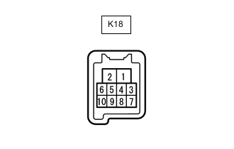
Disconnect the K18 front power window regulator motor assembly LH connector.
-
Measure the voltage and resistance according to the value(s) in the table below.
Tech Tips
Measure the values on the wire harness side with the connector disconnected.
Tester Connection Wiring Color Terminal Description Condition Specified Condition K18-1 (GND) - Body ground LA-W - Body ground Ground Always Below 1 Ω K18-2 (B) - Body ground LA-GR - Body ground Power supply Always 11 to 14 V -
Reconnect the J8 front power window regulator motor assembly RH connector.
-
Measure the voltage according to the value(s) in the table below.
Tester Connection Wiring Color Terminal Description Condition Specified Condition K18-7 (DOWN) - K18-1 (GND) P - LA-W Power window motor DOWN input Ignition switch ON, power window master switch (driver door power window regulator switch) not pushed or pulled 11 to 14 V Ignition switch ON, driver door power window moving, power window master switch (driver door power window regulator switch) pushed halfway down (Manual operation) Below 1 V Ignition switch ON, driver door power window fully closed 11 to 14 V Ignition switch ON, driver door power window moving, power window master switch (driver door power window regulator switch) fully pushed down (Auto operation) Below 1 V Ignition switch ON, driver door power window fully open 11 to 14 V K18-10 (UP) - K18-1 (GND) B - LA-W Power window motor UP input Ignition switch ON, power window master switch (driver door power window regulator switch) not pushed or pulled 11 to 14 V Ignition switch ON, driver door power window moving, power window master switch (driver door power window regulator switch) pulled halfway up (Manual operation) Below 1 V Ignition switch ON, power window master switch (driver door power window regulator switch) fully open 11 to 14 V Ignition switch ON, driver door power window moving, power window master switch (driver door power window regulator switch) fully pulled up (Auto operation) Below 1 V Ignition switch ON, driver door power window fully closed 11 to 14 V
-
-
CHECK REAR POWER WINDOW REGULATOR MOTOR ASSEMBLY LH (w/ Smart Entry and Start System)
-
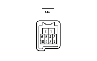
Disconnect the M4 rear power window regulator motor assembly LH connector.
-
Measure the voltage and resistance according to the value(s) in the table below.
Tech Tips
Measure the values on the wire harness side with the connector disconnected.
Tester Connection Wiring Color Terminal Description Condition Specified Condition M4-1 (GND) - Body ground W-B - Body ground Ground Always Below 1 Ω M4-2 (B) - Body ground L - Body ground Power supply Always 11 to 14 V -
Reconnect the M4 rear power window regulator motor assembly LH connector.
-
Measure the voltage according to the value(s) in the table below.
Tester Connection Wiring Color Terminal Description Condition Specified Condition M4-4 (AUTO) - M4-1 (GND) R - W-B Power window motor AUTO UP input Ignition switch ON, rear LH door power window fully open 11 to 14 V Ignition switch ON, rear LH door power window moving, rear power window regulator switch assembly (for Rear LH Door) fully pulled up (Auto operation) Below 1 V Ignition switch ON, rear LH door power window fully closed 11 to 14 V Power window motor AUTO DOWN input Ignition switch ON, rear LH door power window fully closed 11 to 14 V Ignition switch ON, rear LH door power window moving, rear power window regulator switch assembly (for Rear LH Door) fully pushed down (Auto operation) Below 1 V Ignition switch ON, rear LH door power window fully open 11 to 14 V M4-7 (DOWN) - M4-1 (GND) P - W-B Power window motor DOWN input Ignition switch ON, rear power window regulator switch assembly (for Rear LH Door) not pushed or pulled 11 to 14 V Ignition switch ON, rear LH door power window moving, rear power window regulator switch assembly (for Rear LH Door) pushed halfway down (Manual operation) Below 1 V Ignition switch ON, rear LH door power window fully closed 11 to 14 V Ignition switch ON, rear LH door power window moving, rear power window regulator switch assembly (for Rear LH Door) fully pushed down (Auto operation) Below 1 V Ignition switch ON, rear LH door power window fully open 11 to 14 V M4-10 (UP) - M4-1 (GND) B - W-B Power window motor UP input Ignition switch ON, rear power window regulator switch assembly (for Rear LH Door) not pushed or pulled 11 to 14 V Ignition switch ON, rear LH door power window moving, rear power window regulator switch assembly (for Rear LH Door) pulled halfway up (Manual operation) Below 1 V Ignition switch ON, rear LH door power window fully open 11 to 14 V Ignition switch ON, rear LH door power window moving, rear power window regulator switch assembly (for Rear LH Door) fully pulled up (Auto operation) Below 1 V Ignition switch ON, rear LH door power window fully closed 11 to 14 V
-
-
CHECK REAR POWER WINDOW REGULATOR MOTOR ASSEMBLY RH (w/ Smart Entry and Start System)
-

Disconnect the L4 rear power window regulator motor assembly RH connector.
-
Measure the voltage and resistance according to the value(s) in the table below.
Tech Tips
Measure the values on the wire harness side with the connector disconnected.
Tester Connection Wiring Color Terminal Description Condition Specified Condition L4-1 (GND) - Body ground W-B - Body ground Ground Always Below 1 Ω L4-2 (B) - Body ground G - Body ground Power supply Always 11 to 14 V -
Reconnect the L4 rear power window regulator motor assembly RH connector.
-
Measure the voltage according to the value(s) in the table below.
Tester Connection Wiring Color Terminal Description Condition Specified Condition L4-4 (AUTO) - L4-1 (GND) R - W-B Power window motor AUTO UP input Ignition switch ON, rear RH door power window fully open 11 to 14 V Ignition switch ON, rear RH door power window moving, rear power window regulator switch assembly (for Rear RH Door) fully pulled up (Auto operation) Below 1 V Ignition switch ON, rear RH door power window fully closed 11 to 14 V Power window motor AUTO DOWN input Ignition switch ON, rear RH door power window fully closed 11 to 14 V Ignition switch ON, rear RH door power window moving, rear power window regulator switch assembly (for Rear RH Door) fully pushed down (Auto operation) Below 1 V Ignition switch ON, rear RH door power window fully open 11 to 14 V L4-7 (DOWN) - L4-1 (GND) P - W-B Power window motor DOWN input Ignition switch ON, rear power window regulator switch assembly (for Rear RH Door) not pushed or pulled 11 to 14 V Ignition switch ON, rear RH door power window moving, rear power window regulator switch assembly (for Rear RH Door) pushed halfway down (Manual operation) Below 1 V Ignition switch ON, rear RH door power window fully closed 11 to 14 V Ignition switch ON, rear RH door power window moving, rear power window regulator switch assembly (for Rear RH Door) fully pushed down (Auto operation) Below 1 V Ignition switch ON, rear RH door power window fully open 11 to 14 V L4-10 (UP) - L4-1 (GND) B - W-B Power window motor UP input Ignition switch ON, rear power window regulator switch assembly (for Rear RH Door) not pushed or pulled 11 to 14 V Ignition switch ON, rear RH door power window moving, rear power window regulator switch assembly (for Rear RH Door) pulled halfway up (Manual operation) Below 1 V Ignition switch ON, rear RH door power window fully open 11 to 14 V Ignition switch ON, rear RH door power window moving, rear power window regulator switch assembly (for Rear RH Door) fully pulled up (Auto operation) Below 1 V Ignition switch ON, rear RH door power window fully closed 11 to 14 V
-
-
CHECK INSTRUMENT PANEL JUNCTION BLOCK ASSEMBLY AND BODY ECU
Figure 1. for RHD

*1 Instrument Panel Junction Block Assembly - - Figure 2. for LHD
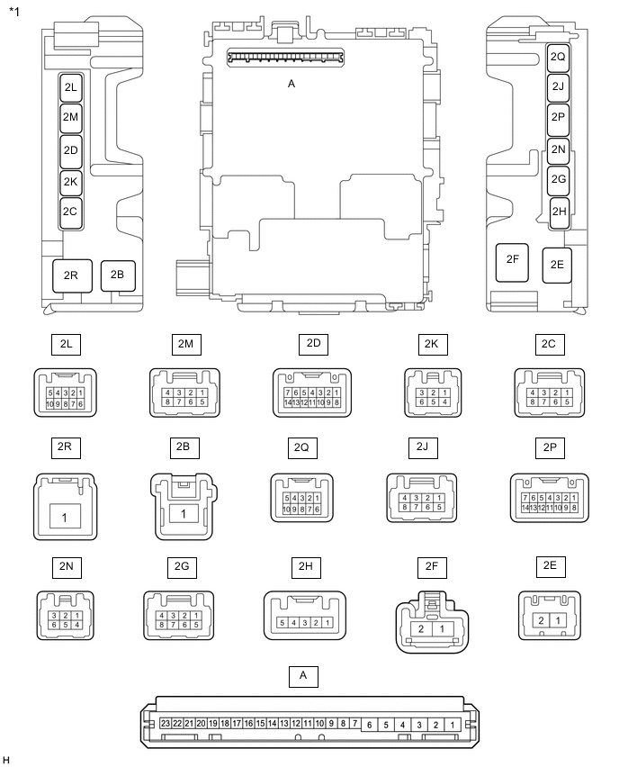
*1 Instrument Panel Junction Block Assembly - - 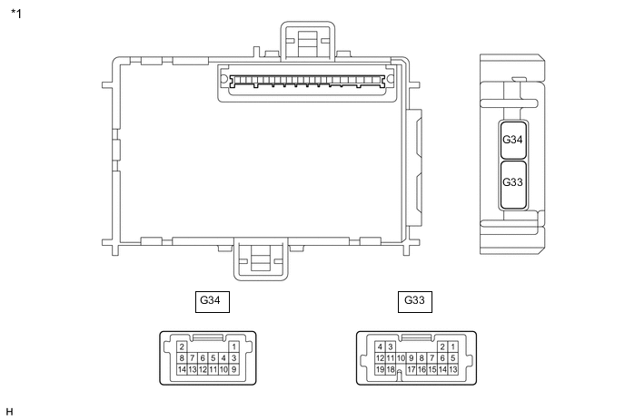
*1 Body ECU - -
-
Remove the body ECU from the instrument panel junction block assembly.
-
Measure the voltage and resistance according to the value(s) in the table below.
Tester Connection Wiring Color Terminal Description Condition Specified Condition A-1 (GND) - Body ground None - Body ground Ground Always Below 1 Ω A-6 (BECU) - Body ground None - Body ground Battery power supply Always 11 to 14 V A-7 (IG) - Body ground None - Body ground IG power supply Ignition switch ON 11 to 14 V Ignition switch off Below 1 V -
Install the body ECU to the instrument panel junction block assembly.
-
Measure the voltage and waveform according to the value(s) in the table below.
Tester Connection Wiring Color Terminal Description Condition Specified Condition G33-14 (PCTY) - Body ground LG - Body ground Front door courtesy light switch assembly LH input Front door LH open Below 1 V Front door LH closed Pulse generation 2L-4 (DCTY) - Body ground R - Body ground Front door courtesy light switch assembly RH input Front door RH open Below 1 V Front door RH closed Pulse generation
-