ROOF HEADLINING REMOVAL
CAUTION / NOTICE / HINT
Tech Tips
-
Use the same procedure for RHD and LHD vehicles.
-
The procedure listed below is for RHD vehicles.
The necessary procedures (adjustment, calibration, initialization or registration) that must be performed after parts are removed, installed or replaced during the roof headlining removal/installation are shown below.
| Replacement Part or Procedure | Necessary Procedures | Effects / Inoperative when not Performed | Link |
|---|---|---|---|
| Disconnect cable from negative battery terminal | w/ Power Back Door System: Reset back door close position |
Power door lock control system |
CAUTION:
Some of these service operations affect the SRS airbag system. Read the precautionary notices concerning the SRS airbag system before servicing.
PROCEDURE
-
PRECAUTION
Note
After turning the ignition switch off, waiting time may be required before disconnecting the cable from the battery terminal. Therefore, make sure to read the disconnecting the cable from the battery terminal notice before proceeding with work.
-
DISCONNECT CABLE FROM NEGATIVE BATTERY TERMINAL
CAUTION:
Wait at least 90 seconds after disconnecting the cable from the negative (-) battery terminal to disable the SRS system.
Note
When disconnecting the cable, some systems need to be initialized after the cable is reconnected.
-
REMOVE REAR NO. 2 SEAT ASSEMBLY LH
-
REMOVE REAR NO. 2 SEAT ASSEMBLY RH
-
REMOVE FRONT ASSIST GRIP SUB-ASSEMBLY
-
REMOVE FRONT PILLAR GARNISH LH
-
REMOVE FRONT PILLAR GARNISH RH
-
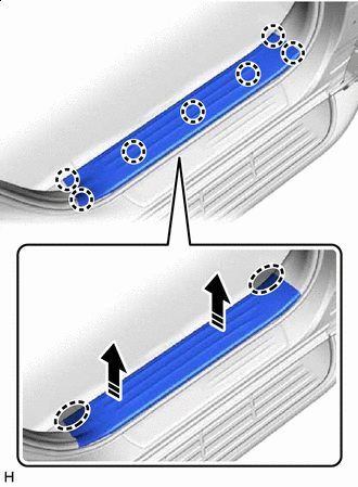
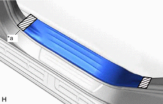
REMOVE FRONT DOOR SCUFF PLATE LH
-
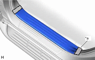
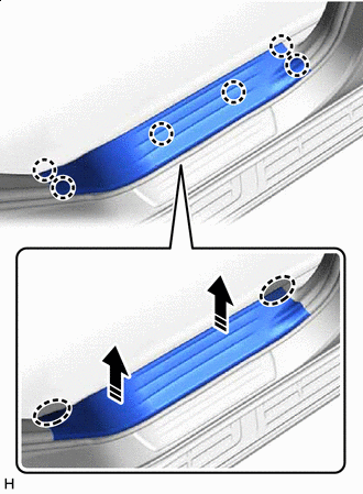
*a Protective Tape Put protective tape around the front door scuff plate LH.
-
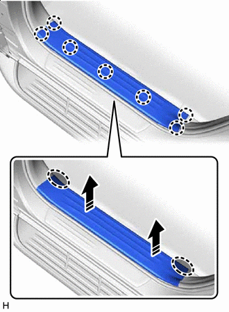

Place Hands Here 
Remove in this Direction Place your hands at the position shown in the illustration and pull as shown to detach the claw and remove the front door scuff plate LH.
-
-
REMOVE FRONT DOOR SCUFF PLATE RH
-
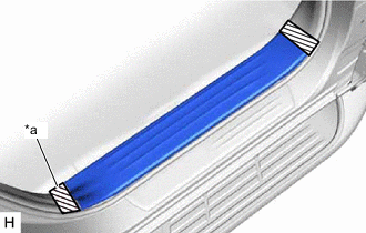
*a Protective Tape Put protective tape around the front door scuff plate RH.
-
Place Hands Here Remove in this Direction Place your hands at the position shown in the illustration and pull as shown to detach the claw and remove the front door scuff plate RH.
-
-
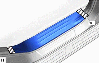
REMOVE REAR DOOR SCUFF PLATE LH
-
*a Protective Tape Put protective tape around the rear door scuff plate LH.
-
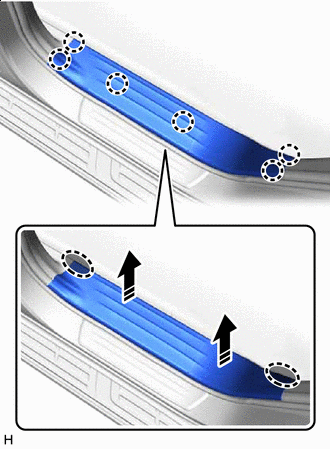
Place Hands Here Remove in this Direction Place your hands at the position shown in the illustration and pull as shown to detach the claw and remove the rear door scuff plate LH.
-
-
REMOVE REAR DOOR SCUFF PLATE RH
-
*a Protective Tape Put protective tape around the rear door scuff plate RH.
-
Place Hands Here Remove in this Direction Place your hands at the position shown in the illustration and pull as shown to detach the claw and remove the rear door scuff plate RH.
-
-
REMOVE OUTER LAP BELT ANCHOR COVER
Tech Tips
Use the same procedure for both outer lap belt anchor covers.
-
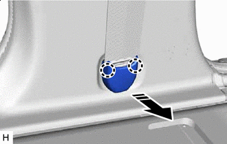
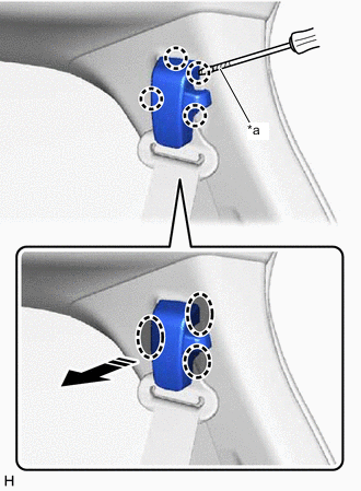
Remove in this Direction Detach the claw and remove the outer lap belt anchor cover as shown in the illustration.
-
-
REMOVE LOWER CENTER PILLAR GARNISH LH
-
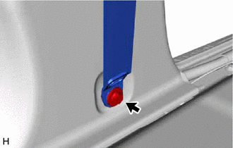
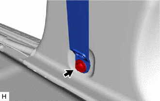
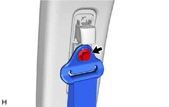
Remove the bolt and disconnect the front seat outer belt assembly LH.
-
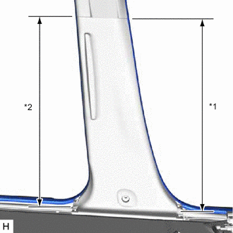
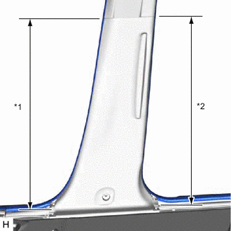
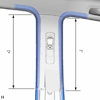
*1 Front Door Opening Trim Weatherstrip LH *2 Rear Door Opening Trim Weatherstrip LH Disconnect the front door opening trim weatherstrip LH and rear door opening trim weatherstrip LH in the range shown in the illustration.
-
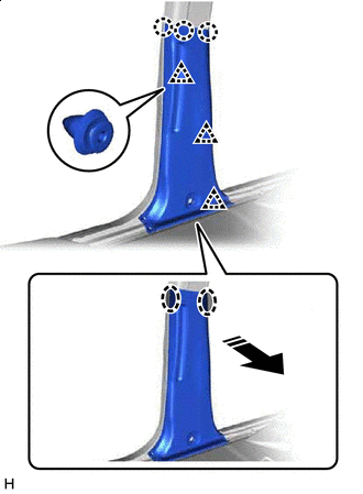
Place Hands Here Remove in this Direction Place your hands at the position shown in the illustration and pull as shown to detach the claw and clip and remove the lower center pillar garnish LH.
-
-
REMOVE LOWER CENTER PILLAR GARNISH RH
-
Remove the bolt and disconnect the front seat outer belt assembly RH.
-
*1 Front Door Opening Trim Weatherstrip RH *2 Rear Door Opening Trim Weatherstrip RH Disconnect the front door opening trim weatherstrip RH and rear door opening trim weatherstrip RH in the range shown in the illustration.
-
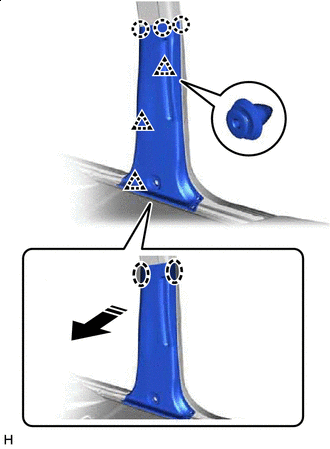
Place Hands Here Remove in this Direction Place your hands at the position shown in the illustration and pull as shown to detach the claw and clip and remove the lower center pillar garnish RH.
-
-
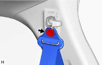
REMOVE SEAT BELT ANCHOR COVER CAP
Tech Tips
Use the same procedure for both seat belt anchor cover caps.
-
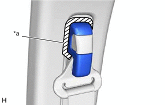
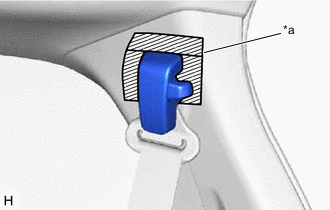
*a Protective Tape Put protective tape around the seat belt anchor cover cap.
-
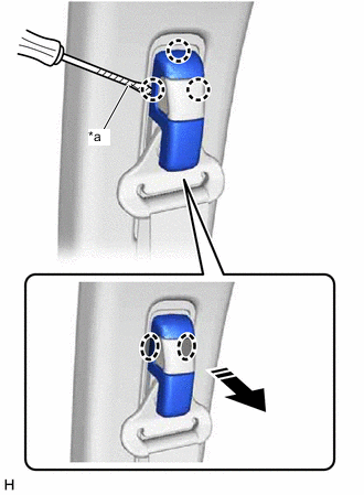
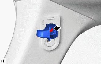
*a Protective Tape Insert Thin-bladed Screwdriver Here Remove in this Direction Insert a thin-bladed screwdriver at the position shown in the illustration and detach the claw and remove the seat belt anchor cover cap.
Tech Tips
Tape the thin-bladed screwdriver tip before use.
-
-
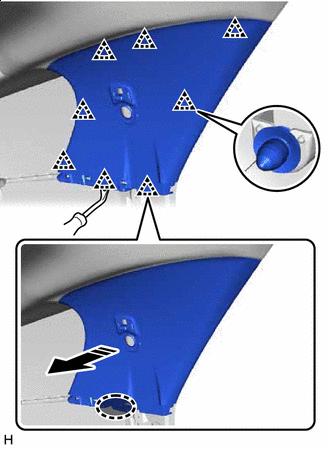
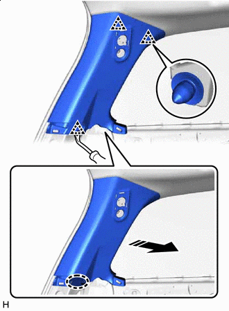
REMOVE UPPER CENTER PILLAR GARNISH LH
-
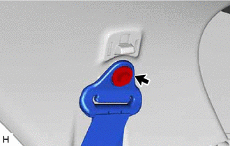
Remove the bolt and disconnect the front seat outer belt assembly LH.
-
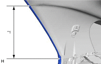
*1 Front Door Opening Trim Weatherstrip LH *2 Rear Door Opening Trim Weatherstrip LH Disconnect the front door opening trim weatherstrip LH and rear door opening trim weatherstrip LH in the range shown in the illustration.
-
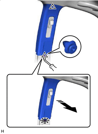
Insert Clip Remover Here Remove in this Direction Insert a clip remover at the position shown in the illustration and pull as shown to detach the clip and remove the upper center pillar garnish LH.
-
-
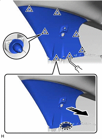
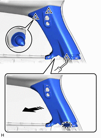
REMOVE UPPER CENTER PILLAR GARNISH RH
-
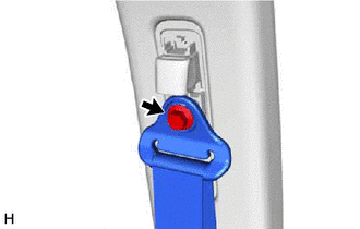
Remove the bolt and disconnect the front seat outer belt assembly RH.
-
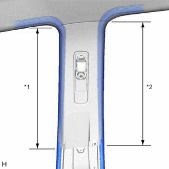
*1 Front Door Opening Trim Weatherstrip RH *2 Rear Door Opening Trim Weatherstrip RH Disconnect the front door opening trim weatherstrip RH and rear door opening trim weatherstrip RH in the range shown in the illustration.
-
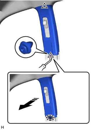
Insert Clip Remover Here Remove in this Direction Insert a clip remover at the position shown in the illustration and pull as shown to detach the clip and remove the upper center pillar garnish RH.
-
-
REMOVE BACK DOOR SCUFF PLATE
-
Put protective tape around the back door scuff plate.
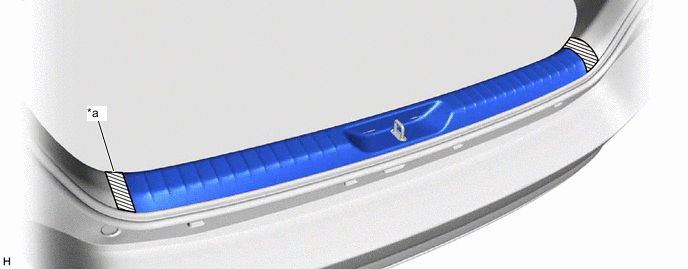
*a Protective Tape - - -
Place your hands at the position shown in the illustration and pull as shown to detach the claw and clip and remove the back door scuff plate.
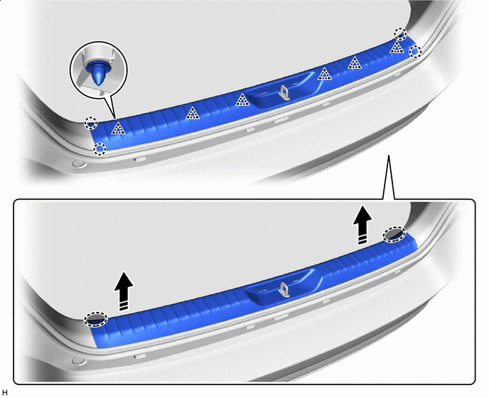
Place Hands Here Remove in this Direction
-
-
REMOVE REAR NO. 1 SEAT OUTER LAP BELT ANCHOR COVER
Tech Tips
Use the same procedure for both rear No. 1 seat outer lap belt anchor covers.
-
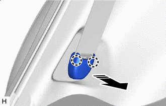
Remove in this Direction Detach the claw and remove the rear No. 1 seat outer lap belt anchor cover as shown in the illustration.
-
-
REMOVE REAR NO. 2 SEAT OUTER LAP BELT ANCHOR COVER
Tech Tips
Use the same procedure for both rear No. 2 seat outer lap belt anchor covers.
-
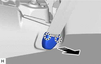
Remove in this Direction Detach the claw and remove the rear No. 2 seat outer lap belt anchor cover as shown in the illustration.
-
-
REMOVE QUARTER INSIDE TRIM BOARD LH
-
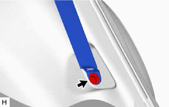
Remove the bolt and disconnect the rear No. 1 seat outer belt assembly LH.
-
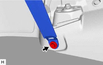
Remove the bolt and disconnect the rear No. 2 seat outer belt assembly LH.
-
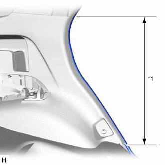
*1 Rear Door Opening Trim Weatherstrip LH Disconnect the rear door opening trim weatherstrip LH in the range shown in the illustration.
-
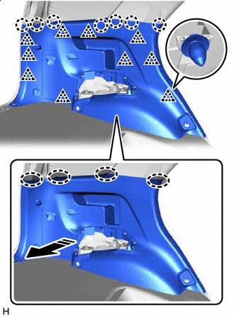
Place Hands Here Remove in this Direction Place your hands at the position shown in the illustration and pull as shown to detach the claw and clip and remove the quarter inside trim board LH.
-
-
REMOVE QUARTER INSIDE TRIM BOARD RH
-
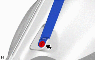
Remove the bolt and disconnect the rear No. 1 seat outer belt assembly RH.
-
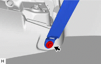
Remove the bolt and disconnect the rear No. 2 seat outer belt assembly RH.
-
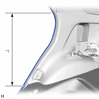
*1 Rear Door Opening Trim Weatherstrip RH Disconnect the rear door opening trim weatherstrip RH in the range shown in the illustration.
-
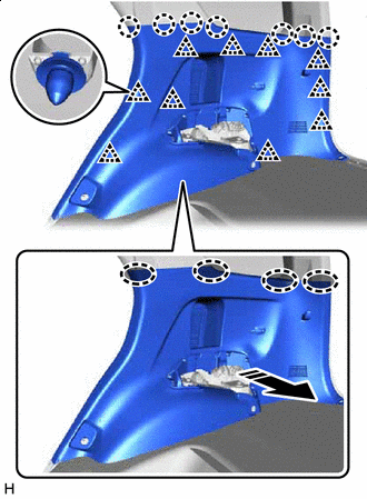
Place Hands Here Remove in this Direction Place your hands at the position shown in the illustration and pull as shown to detach the claw and clip.
-
Disconnect the connector and remove the quarter inside trim board RH.
-
-
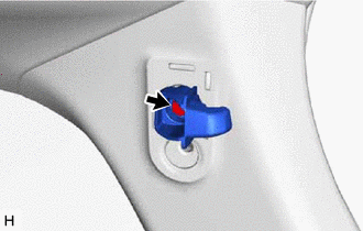
REMOVE SEAT BELT ANCHOR COVER CAP
Tech Tips
Use the same procedure for both seat belt anchor cover caps.
-
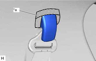
*a Protective Tape Put protective tape around the seat belt anchor cover cap.
-
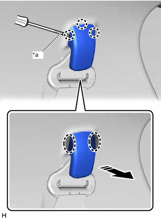
*a Protective Tape Insert Thin-bladed Screwdriver Here Remove in this Direction Insert a thin-bladed screwdriver at the position shown in the illustration and detach the claw and remove the seat belt anchor cover cap.
Tech Tips
Tape the thin-bladed screwdriver tip before use.
-
-
REMOVE QUARTER PILLAR GARNISH LH
-
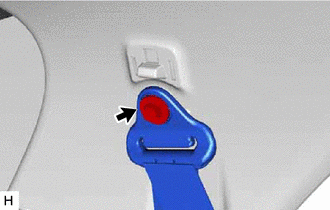
Remove the bolt and disconnect the rear No. 1 seat outer belt assembly LH.
-
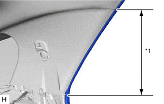
*1 Rear Door Opening Trim Weatherstrip LH Disconnect the rear door opening trim weatherstrip LH in the range shown in the illustration.
-
Insert Clip Remover Here Remove in this Direction Insert a clip remover at the position shown in the illustration and pull as shown to detach the clip and remove the quarter pillar garnish LH.
-
-
REMOVE QUARTER PILLAR GARNISH RH
-
Remove the bolt and disconnect the rear No. 1 seat outer belt assembly RH.
-
*1 Rear Door Opening Trim Weatherstrip RH Disconnect the rear door opening trim weatherstrip RH in the range shown in the illustration.
-
Insert Clip Remover Here Remove in this Direction Insert a clip remover at the position shown in the illustration and pull as shown to detach the clip and remove the quarter pillar garnish RH.
-
-
REMOVE SEAT BELT ANCHOR COVER CAP
Tech Tips
Use the same procedure for both seat belt anchor cover caps.
-
*a Protective Tape Put protective tape around the seat belt anchor cover cap.
-
*a Protective Tape Insert Thin-bladed Screwdriver Here Remove in this Direction Insert a thin-bladed screwdriver at the position shown in the illustration and detach the claw and remove the seat belt anchor cover cap.
Tech Tips
Tape the thin-bladed screwdriver tip before use.
-
-
REMOVE UPPER REAR PILLAR GARNISH LH
-
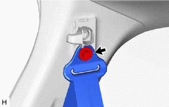
Remove the bolt and disconnect the rear No. 2 seat outer belt assembly LH.
-
Remove the bolt and rear seat hook.
-
Insert Clip Remover Here Remove in this Direction Insert a clip remover at the position shown in the illustration and pull as shown to detach the clip and remove the upper rear pillar garnish LH.
-
-
REMOVE UPPER REAR PILLAR GARNISH RH
-
Remove the bolt and disconnect the rear No. 2 seat outer belt assembly RH.
-
Remove the bolt and rear seat hook.
-
Insert Clip Remover Here Remove in this Direction Insert a clip remover at the position shown in the illustration and pull as shown to detach the clip and remove the upper rear pillar garnish RH.
-
-
REMOVE MAP LIGHT ASSEMBLY
-
for LED Type, for LHD:
-
for Bulb Type:
-
-
REMOVE SPOT LIGHT ASSEMBLY
-
REMOVE NO. 1 ROOM LIGHT ASSEMBLY
-
REMOVE REAR SEAT BELT COVER
-
Insert Moulding Remover D Here Remove in this Direction Insert moulding remover D at the position shown in the illustration and pull as shown to detach the clip, claw and guide and remove the rear seat belt cover.
-
-
REMOVE VISOR BRACKET COVER LH
-
Open the visor assembly LH.
-
*a Protective Tape Insert Thin-bladed Screwdriver Here Insert a thin-bladed screwdriver at the position shown in the illustration and detach the claw and remove the visor bracket cover LH.
Tech Tips
Tape the thin-bladed screwdriver tip before use.
-
-
REMOVE VISOR BRACKET COVER RH
-
Open the visor assembly RH.
-
*a Protective Tape Insert Thin-bladed Screwdriver Here Insert a thin-bladed screwdriver at the position shown in the illustration and detach the claw and remove the visor bracket cover RH.
Tech Tips
Tape the thin-bladed screwdriver tip before use.
-
-
REMOVE VISOR ASSEMBLY LH
-
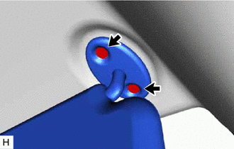
Remove the 2 screws.
-
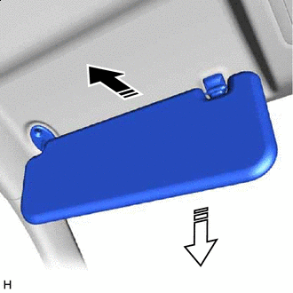
Remove in this Direction (1) 
Remove in this Direction (2) Pull in the direction (1) shown in the illustration to disconnect the visor assembly LH from the visor holder.
-
Pull in the direction (2) shown in the illustration to remove the visor assembly LH.
-
-
REMOVE VISOR ASSEMBLY RH
-
Remove the 2 screws.
-
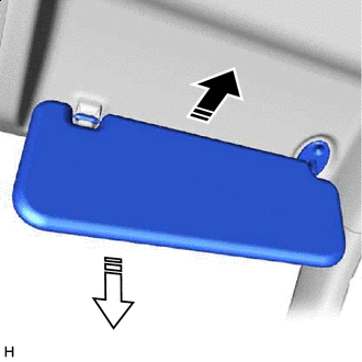
Remove in this Direction (1) Remove in this Direction (2) Pull in the direction (1) shown in the illustration to disconnect the visor assembly RH from the visor holder.
-
Pull in the direction (2) shown in the illustration to remove the visor assembly RH.
-
-
REMOVE VISOR HOLDER
Tech Tips
Use the same procedure for both visor holders.
-
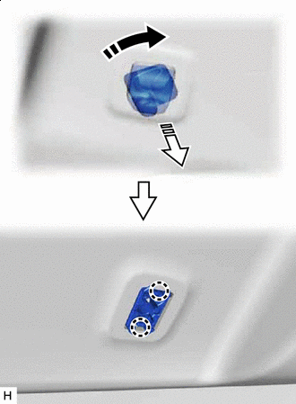
Remove in this Direction (1) Remove in this Direction (2) Turn the visor holder clockwise approximately 45° and pull it out as shown in the illustration.
-
Detach the claw and remove the visor holder.
-
-
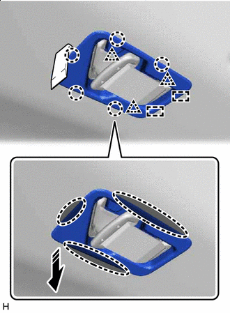
REMOVE ASSIST GRIP SUB-ASSEMBLY
Tech Tips
Use the same procedure for all assist grip sub-assemblies.
-
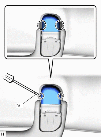
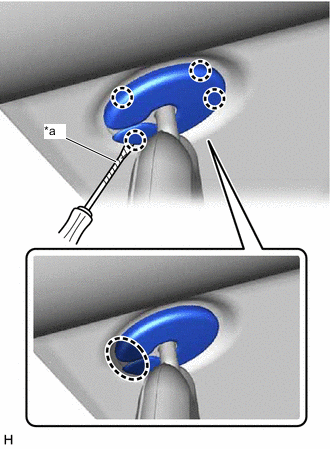
*a Protective Tape Insert Thin-bladed Screwdriver Here Insert a thin-bladed screwdriver at the position shown in the illustration and detach the claw and remove the assist grip cover.
Tech Tips
-
Use the same procedure for both assist grip covers.
-
Tape the thin-bladed screwdriver tip before use.
-
-
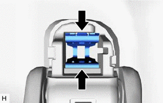
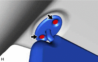
Pinch the clip with needle-nose pliers.
Tech Tips
Use the same procedure for both clips.
-
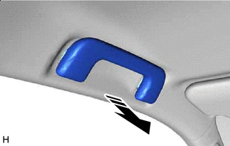
Remove in this Direction Hold the handle and pull as shown in the illustration to remove the assist grip sub-assembly.
-
Using needle-nose pliers, remove the clip.
-
-
REMOVE REAR ASSIST GRIP ASSEMBLY
Tech Tips
Use the same procedure for both rear assist grip assemblies.
-
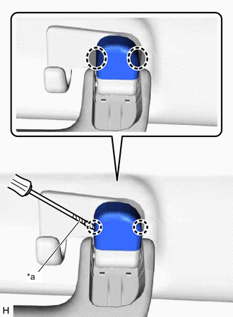
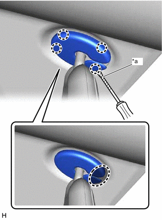
*a Protective Tape Insert Thin-bladed Screwdriver Here Insert a thin-bladed screwdriver at the position shown in the illustration and detach the claw and remove the assist grip cover.
Tech Tips
-
Use the same procedure for both assist grip covers.
-
Tape the thin-bladed screwdriver tip before use.
-
-
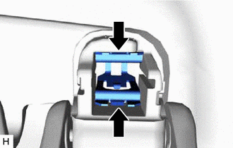
Pinch the clip with needle-nose pliers.
Tech Tips
Use the same procedure for both clips.
-
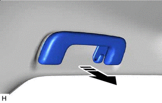
Remove in this Direction Hold the handle and pull as shown in the illustration to remove the rear assist grip assembly.
-
Using needle-nose pliers, remove the clip.
-
-
REMOVE ROOF HEADLINING ASSEMBLY
-
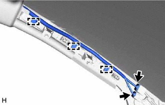
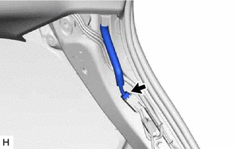
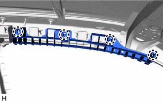
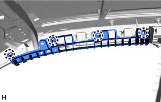
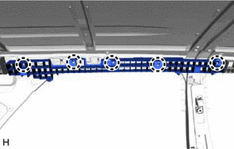
Disconnect the connector and detach the clamp from the front pillar LH.
-
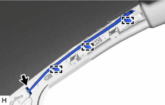
Disconnect the connector and detach the clamp from the front pillar RH.
-
Disconnect the connector from the rear pillar RH.
-
Disconnect the front door opening trim weatherstrip LH and rear door opening trim weatherstrip LH in the range shown in the illustration.
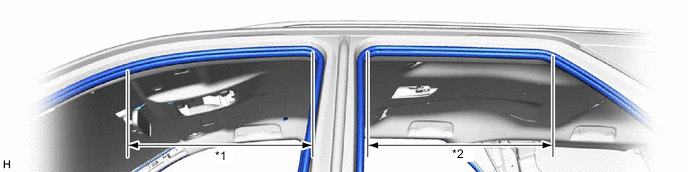
*1 Front Door Opening Trim Weatherstrip LH *2 Rear Door Opening Trim Weatherstrip LH -
Disconnect the front door opening trim weatherstrip RH and rear door opening trim weatherstrip RH in the range shown in the illustration.
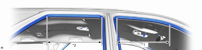
*1 Front Door Opening Trim Weatherstrip RH *2 Rear Door Opening Trim Weatherstrip RH -
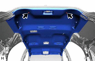
Using a clip remover, remove the 2 clips.
-
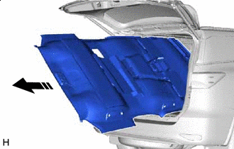
Remove in this Direction Turn the roof headlining assembly diagonally and bend slightly to remove it from the back door.
Note
-
Make sure wrinkles do not form in the roof headlining assembly during removal.
-
Make sure that the roof headlining assembly does not get caught on anything as it may become bent or damaged.
-
Do not damage the roof headlining assembly or vehicle interior.
-
-
-
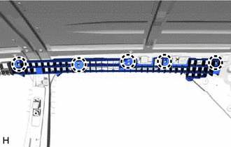
REMOVE FRONT SIDE RAIL SPACER LH (w/o Curtain Shield Airbag)
-
Detach the claw and remove the front side rail spacer LH.
-
-
REMOVE FRONT SIDE RAIL SPACER RH (w/o Curtain Shield Airbag)
-
Detach the claw and remove the front side rail spacer RH.
-
-
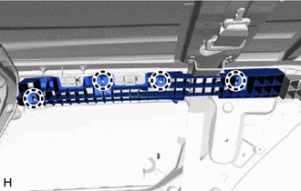
REMOVE REAR SIDE RAIL SPACER LH (w/o Curtain Shield Airbag)
-
Detach the claw and remove the rear side rail spacer LH.
-
-
REMOVE REAR SIDE RAIL SPACER RH (w/o Curtain Shield Airbag)
-
Detach the claw and remove the rear side rail spacer RH.
-
-
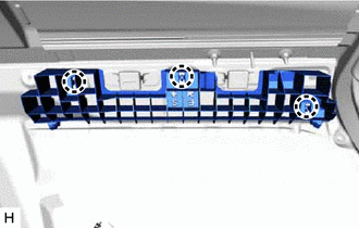
REMOVE REAR NO. 2 SIDE RAIL SPACER LH (w/o Curtain Shield Airbag)
-
Detach the claw and remove the rear No. 2 side rail spacer LH.
-
-
REMOVE REAR NO. 2 SIDE RAIL SPACER RH (w/o Curtain Shield Airbag)
-
Detach the claw and remove the rear No. 2 side rail spacer RH.
-