FRONT PROPELLER SHAFT ASSEMBLY(for TSAM Made) REASSEMBLY

CAUTION / NOTICE / HINT
Note
-
When using a vise, place aluminum plates between the part and vise.
-
When using a vise, do not overtighten it.
PROCEDURE
-
INSTALL UNIVERSAL JOINT SPIDER ASSEMBLY
Tech Tips
Use the same procedure for both universal joint spider assemblies.
-
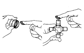
Apply grease to a new spider and new spider bearings.
Grease Lithium base chassis grease NLGI No. 2 Note
Do not apply too much grease.
-
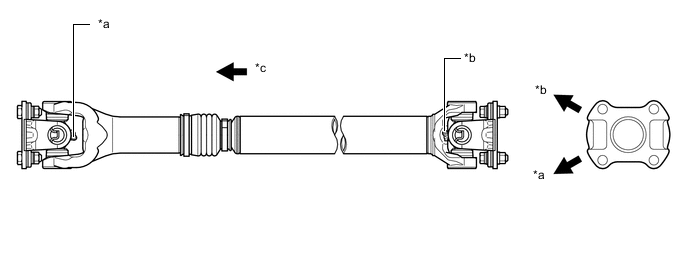
Install the spider to the flange yoke.
-
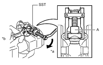
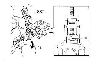
*a Turn *b Hold Using SST, install 2 of the spider bearings to the universal joint spider assembly.
- SST
- 09332-25010
Tech Tips
Before installing SST, sufficiently raise the part labeled A. If the part labeled A is too low, it may be difficult to install SST.
-
Using SST, adjust both spider bearings so that the snap ring grooves are as wide as possible and equal in width.
- SST
- 09332-25010
-
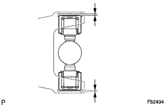
Install 2 new snap rings to the installed spider bearings. The snap rings must have equal thickness and allow 0 to 0.05 mm (0 to 0.00196 in.) of axial play.
Note
While the installed snap rings should have equal thickness, if the axial play is greater than 0.05 mm (0.00196 in.), select 2 snap rings that have as close to the same thickness as possible.
Tech Tips
Do not reuse the snap rings.
Standard Snap Ring Thickness Part No. Color Thickness 90080-52044 Green 1.384 mm (0.0545 in.) 90080-52174 Green 1.39 mm (0.0547 in.) 90080-52043 Red 1.435 mm (0.0565 in.) 90080-52175 Orange 1.44 mm (0.0567 in.) 90080-52041 Black 1.486 mm (0.0585 in.) 90080-52176 Black 1.49 mm (0.0587 in.) 90080-52042 Copper 1.511 mm (0.0595 in.) 90080-52040 Silver 1.537 mm (0.0605 in.) 90080-52177 White 1.54 mm (0.0606 in.) 90080-52039 Yellow 1.588 mm (0.0625 in.) 90080-52178 Yellow 1.59 mm (0.0626 in.) 90080-52038 Blue 1.638 mm (0.0645 in.) 90080-52179 Red 1.64 mm (0.0646 in.) 90080-52180 Blue 1.69 mm (0.0665 in.) Note
-
Use a new snap ring.
-
Use a snap ring with as close to the same thickness as possible on both ends.
-
-
*a Hammering Point Using a hammer, tap the flange yoke until there is no clearance between the spider bearing outer race and snap ring.
Tech Tips
Install the spider bearing on the sleeve side using the procedure described above.
-
Align the matchmarks on the flange yoke and front propeller shaft assembly.
-
*a Turn *b Hold Using SST, install the 2 spider bearings to the universal joint spider assembly.
- SST
- 09332-25010
Tech Tips
Before installing SST, sufficiently raise the part labeled A. If the part labeled A is too low, it may be difficult to install SST.
-
Using SST, adjust both spider bearings so that the snap ring grooves are as wide as possible and equal in width.
- SST
- 09332-25010
-
Install 2 new snap rings to the installed spider bearings. The snap rings must have equal thickness and allow 0 to 0.05 mm (0 to 0.00196 in.) of axial play.
Note
While the installed snap rings should have equal thickness, if the axial play is greater than 0.05 mm (0.00196 in.), select 2 snap rings that have as close to the same thickness as possible.
Tech Tips
Do not reuse the snap rings.
Standard Snap Ring Thickness Part No. Color Thickness 90080-52044 Green 1.384 mm (0.0545 in.) 90080-52174 Green 1.39 mm (0.0547 in.) 90080-52043 Red 1.435 mm (0.0565 in.) 90080-52175 Orange 1.44 mm (0.0567 in.) 90080-52041 Black 1.486 mm (0.0585 in.) 90080-52176 Black 1.49 mm (0.0587 in.) 90080-52042 Copper 1.511 mm (0.0595 in.) 90080-52040 Silver 1.537 mm (0.0605 in.) 90080-52177 White 1.54 mm (0.0606 in.) 90080-52039 Yellow 1.588 mm (0.0625 in.) 90080-52178 Yellow 1.59 mm (0.0626 in.) 90080-52038 Blue 1.638 mm (0.0645 in.) 90080-52179 Red 1.64 mm (0.0646 in.) 90080-52180 Blue 1.69 mm (0.0665 in.) Note
-
Use a new snap ring.
-
Use snap rings with as close to the same thickness as possible on both ends.
-
-
*a Hammering Point Using a hammer, tap the front propeller shaft assembly until there is no clearance between the spider bearing outer race and snap ring.
Tech Tips
Install the spider bearing on the sleeve side using the procedure described above.
-
-
INSTALL SLIDING SHAFT BOOT
-
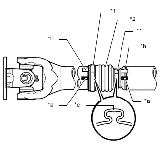
*1 Propeller Shaft Boot Clamp *2 Sliding Shaft Boot *a Matchmark of Front Propeller Shaft Assembly and Sleeve Yoke *b Matchmark of Pinching Portion of Propeller Shaft Boot Clamp *c Pinching Portion Temporarily install a new sliding shaft boot to the front propeller shaft assembly with 2 new propeller shaft boot clamps.
-
Coat the splines of the front propeller shaft assembly with MP grease.
Standard Grease Capacity 7.0 to 10.0 g (0.25 to 0.35 oz) -
Align the matchmarks on the front propeller shaft assembly and sleeve yoke.
-
Install the sleeve yoke to the front propeller shaft assembly and connect the sliding shaft boot.
-
Align the matchmarks on the front propeller shaft assembly, sleeve yoke and the pinching portions of the 2 propeller shaft boot clamps.
Tech Tips
Make sure to align the matchmarks of the propeller shaft boot clamp.
If the pinching portions are installed at different locations than where they were located before disassembly, the rotational balance of the front propeller shaft assembly cannot be ensured, which may result in vibrations and noise.
-
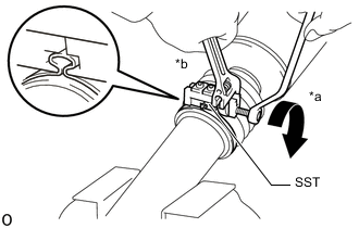
*a Turn *b Hold Secure one of the propeller shaft boot clamps to the sliding shaft boot.
Tech Tips
-
Use the same procedure for each propeller shaft boot clamp.
-
Make sure that the matchmarks of the pinching portion of the propeller shaft boot clamp are aligned.
-
Install SST to the propeller shaft boot clamp, and then while pressing the sliding shaft boot, slightly tighten the SST bolt.
- SST
- 09521-24010
Note
-
Correctly set the propeller shaft boot clamp to the guide groove.
-
Do not damage the sliding shaft boot.
-
Tighten SST so that the propeller shaft boot clamp is pinched.
Standard clearance 0.8 mm (0.0314 in.) or less Note
-
When tightening SST, make sure the clearance of the propeller shaft boot clamp is within the standard clearance.
-
Do not damage the sliding shaft boot.
-
-
Remove SST from the propeller shaft boot clamp.
-
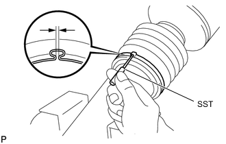
Using SST, measure the clearance of the propeller shaft boot clamp.
- SST
- 09240-00020
Standard clearance 0.8 mm (0.0314 in.) or less Note
If the measured value exceeds the specified value, retighten the propeller shaft boot clamp.
-
-
-
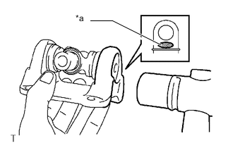
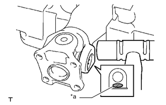
INSPECT PROPELLER SHAFT GREASE FITTING DIRECTION
Tech Tips
-
When replacing a spider bearing, be sure that the grease fitting hole is facing the direction shown in the illustration.
-
Fill the grease fittings with grease.
Grease Lithium base chassis grease NLGI No. 2
*a No. 1 Grease Fitting *b No. 2 Grease Fitting *c Rear Side - - -
-
INSPECT SPIDER BEARING