PROPELLER SHAFT ASSEMBLY(for TMMIN Made) REASSEMBLY

CAUTION / NOTICE / HINT
Note
-
When using a vise, place aluminum plates between the part and vise.
-
When using a vise, do not overtighten it.
CAUTION / NOTICE / HINT
Tech Tips
The following chart describes vehicle types A and B, which are referred to throughout the procedure.
| Vehicle Type A | Vehicle Type B | ||
|---|---|---|---|
| Engine Type | Transmission Type | Engine Type | Transmission Type |
| 2GD-FTV | RC60F | 1GD-FTV | AC60F |
| AC60F | 1GR-FE | AC60F | |
| 2TR-FE | AC60F | - | - |
| R151F | - | - | |
PROCEDURE
-
INSTALL CENTER NO. 1 SUPPORT BEARING ASSEMBLY (for Pre-Runner)
-
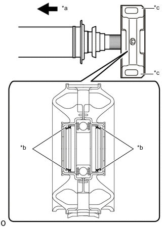
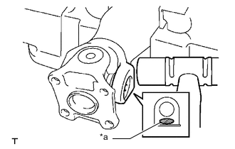
*a Front Side *b Seal *c Cutout Install the center No. 1 support bearing assembly to the intermediate shaft.
Note
-
Carefully insert the part so that the seal does not invert.
-
Make sure to install the part so that the cutouts face the rear of the vehicle.
-
-
Install the 2 washers.
-
w/ flange coupling:
-
*a Matchmark Align the matchmarks on the flange coupling and intermediate shaft, and then install the flange coupling to the intermediate shaft.
-
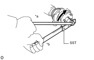
*a Turn *b Hold Using SST to hold the flange coupling, install a new lock nut.
- SST
- 09330-00021
- Torque:
- 73.6 N*m { 751 kgf*cm, 54 ft.*lbf }
-
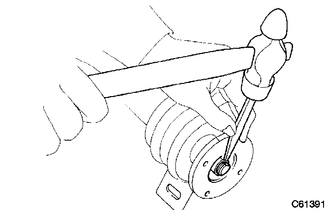
Using a chisel and hammer, stake the lock nut.
Note
-
Fully stake the lock nut along the entire groove.
-
Do not damage the threads of the intermediate shaft.
-
-
-
w/o flange coupling:
-
*a Matchmark Align the matchmarks on the center yoke and intermediate shaft, and then install the center yoke to the intermediate shaft.
-
Install a new lock nut.
- Torque:
- 101.5 N*m { 1035 kgf*cm, 75 ft.*lbf }
-
Using a chisel and hammer, stake the lock nut.
Note
-
Fully stake the lock nut along the entire groove.
-
Do not damage the threads of the intermediate shaft.
-
-
-
-
INSTALL CENTER NO. 1 SUPPORT BEARING ASSEMBLY (for 4WD)
-
*a Front Side *b Seal *c Cutout Install the center No. 1 support bearing assembly to the intermediate shaft.
Note
-
Carefully insert the part so that the seal does not invert.
-
Make sure to install the part so that the cutouts face the rear of the vehicle.
-
-
Install the 2 washers.
-
w/ flange coupling:
-
*a Matchmark Align the matchmarks on the flange coupling and intermediate shaft, and then install the flange coupling to the intermediate shaft.
-
*a Turn *b Hold Using SST to hold the flange coupling, install a new lock nut.
- SST
- 09330-00021
- Torque:
- 73.6 N*m { 751 kgf*cm, 54 ft.*lbf }
-
Using a chisel and hammer, stake the lock nut.
Note
-
Fully stake the lock nut along the entire groove.
-
Do not damage the threads of the intermediate shaft.
-
-
-
w/o flange coupling:
-
*a Matchmark Align the matchmarks on the center yoke and intermediate shaft, and then install the center yoke to the intermediate shaft.
-
Install a new lock nut.
- Torque:
- for Vehicle Type A
- 73.6 N*m { 751 kgf*cm, 54 ft.*lbf }
- for Vehicle Type B
- 101.5 N*m { 1035 kgf*cm, 75 ft.*lbf }
-
Using a chisel and hammer, stake the lock nut.
Note
-
Fully stake the lock nut along the entire groove.
-
Do not damage the threads of the intermediate shaft.
-
-
-
-
INSTALL SPIDER BEARING
Tech Tips
Use the same procedure for all spiders.
-
Apply grease to a new spider and new spider bearings.
Grease Lithium base chassis grease NLGI No. 2 Note
Do not apply too much grease.
-
Install the spider to the flange yoke.
-
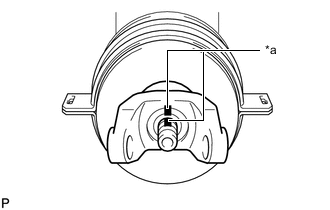
*a Turn *b Hold Using SST, install 2 of the spider bearings to the spider.
- SST
- 09332-25010
-
Using SST, adjust both spider bearings so that the snap ring grooves are as wide as possible and equal in width.
- SST
- 09332-25010
-
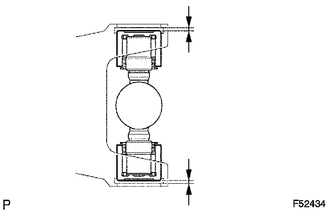
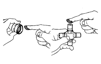
Install 2 new snap rings to the installed spider bearings. The snap rings must have equal thickness and allow 0 to 0.05 mm (0 to 0.00196 in.) of axial play.
Note
While the installed snap rings should have equal thickness, if the axial play is greater than 0.05 mm (0.00196 in.), select 2 snap rings that have as close to the same thickness as possible.
Tech Tips
Do not reuse the snap rings.
Standard Snap Ring Thickness (for Pre-Runner (w/ flange coupling)) Part No. Mark Thickness 90520-T0007 F 2.18 to 2.20 mm (0.0859 to 0.0866 in.) 90520-T0008 G 2.20 to 2.22 mm (0.0867 to 0.0874 in.) 90520-T0009 H 2.22 to 2.24 mm (0.0875 to 0.0881 in.) 90520-T0010 J 2.24 to 2.26 mm (0.0882 to 0.0889 in.) 90520-T0011 K 2.26 to 2.28 mm (0.0890 to 0.0897 in.) 90520-T0012 1 2.28 to 2.30 mm (0.0898 to 0.0905 in.) 90520-T0013 2 2.30 to 2.32 mm (0.0906 to 0.0913 in.) 90520-T0014 3 2.32 to 2.34 mm (0.0914 to 0.0921 in.) 90520-T0015 4 2.34 to 2.36 mm (0.0922 to 0.0929 in.) 90520-T0016 5 2.36 to 2.38 mm (0.0930 to 0.0937 in.) 90520-T0017 6 2.38 to 2.40 mm (0.0938 to 0.0944 in.) 90520-T0018 7 2.40 to 2.42 mm (0.0945 to 0.0952 in.) 90520-T0019 8 2.42 to 2.44 mm (0.0953 to 0.0960 in.) 90520-T0020 N 2.44 to 2.46 mm (0.0961 to 0.0968 in.) 90520-T0021 10 2.46 to 2.48 mm (0.0969 to 0.0976 in.) 90520-T0022 A 2.48 to 2.50 mm (0.0977 to 0.0984 in.) 90520-T0023 B 2.50 to 2.52 mm (0.0985 to 0.0992 in.) 90520-T0024 C 2.52 to 2.54 mm (0.0993 to 0.0999 in.) 90520-T0025 D 2.54 to 2.56 mm (0.1000 to 0.1007 in.) 90520-T0026 E 2.56 to 2.58 mm (0.1008 to 0.1015 in.) Standard Snap Ring Thickness (for Pre-Runner (w/o flange coupling)) Part No. Mark Thickness 90520-T0223 A 1.985 to 2.015 mm (0.0782 to 0.0793 in.) 90520-T0224 B 2.015 to 2.045 mm (0.0794 to 0.0805 in.) 90520-T0225 C 2.045 to 2.075 mm (0.0806 to 0.0816 in.) 90520-T0226 D 2.075 to 2.105 mm (0.0817 to 0.0828 in.) 90520-T0227 1 1.98 to 2.00 mm (0.0780 to 0.0787 in.) 90520-T0228 2 2.00 to 2.02 mm (0.0788 to 0.0795 in.) 90520-T0229 3 2.02 to 2.04 mm (0.0796 to 0.0803 in.) 90520-T0230 4 2.04 to 2.06 mm (0.0804 to 0.0811 in.) 90520-T0231 5 2.06 to 2.08 mm (0.0812 to 0.0818 in.) 90520-T0232 6 2.08 to 2.10 mm (0.0819 to 0.0826 in.) 90520-T0233 7 2.10 to 2.12 mm (0.0827 to 0.0834 in.) 90520-T0234 8 2.12 to 2.14 mm (0.0835 to 0.0842 in.) 90520-T0235 N 2.14 to 2.16 mm (0.0843 to 0.0850 in.) 90520-T0236 10 2.16 to 2.18 mm (0.0851 to 0.0858 in.) Standard Snap Ring Thickness (for 4WD (w/ flange coupling)) Part No. Mark Thickness 90520-T0007 F 2.18 to 2.20 mm (0.0859 to 0.0866 in.) 90520-T0008 G 2.20 to 2.22 mm (0.0867 to 0.0874 in.) 90520-T0009 H 2.22 to 2.24 mm (0.0875 to 0.0881 in.) 90520-T0010 J 2.24 to 2.26 mm (0.0882 to 0.0889 in.) 90520-T0011 K 2.26 to 2.28 mm (0.0890 to 0.0897 in.) 90520-T0012 1 2.28 to 2.30 mm (0.0898 to 0.0905 in.) 90520-T0013 2 2.30 to 2.32 mm (0.0906 to 0.0913 in.) 90520-T0014 3 2.32 to 2.34 mm (0.0914 to 0.0921 in.) 90520-T0015 4 2.34 to 2.36 mm (0.0922 to 0.0929 in.) 90520-T0016 5 2.36 to 2.38 mm (0.0930 to 0.0937 in.) 90520-T0017 6 2.38 to 2.40 mm (0.0938 to 0.0944 in.) 90520-T0018 7 2.40 to 2.42 mm (0.0945 to 0.0952 in.) 90520-T0019 8 2.42 to 2.44 mm (0.0953 to 0.0960 in.) 90520-T0020 N 2.44 to 2.46 mm (0.0961 to 0.0968 in.) 90520-T0021 10 2.46 to 2.48 mm (0.0969 to 0.0976 in.) 90520-T0022 A 2.48 to 2.50 mm (0.0977 to 0.0984 in.) 90520-T0023 B 2.50 to 2.52 mm (0.0985 to 0.0992 in.) 90520-T0024 C 2.52 to 2.54 mm (0.0993 to 0.0999 in.) 90520-T0025 D 2.54 to 2.56 mm (0.1000 to 0.1007 in.) 90520-T0026 E 2.56 to 2.58 mm (0.1008 to 0.1015 in.) Standard Snap Ring Thickness (for 4WD (w/o flange coupling)) for Vehicle Type A Part No. Mark Thickness 90520-T0007 F 2.18 to 2.20 mm (0.0859 to 0.0866 in.) 90520-T0008 G 2.20 to 2.22 mm (0.0867 to 0.0874 in.) 90520-T0009 H 2.22 to 2.24 mm (0.0875 to 0.0881 in.) 90520-T0010 J 2.24 to 2.26 mm (0.0882 to 0.0889 in.) 90520-T0011 K 2.26 to 2.28 mm (0.0890 to 0.0897 in.) 90520-T0012 1 2.28 to 2.30 mm (0.0898 to 0.0905 in.) 90520-T0013 2 2.30 to 2.32 mm (0.0906 to 0.0913 in.) 90520-T0014 3 2.32 to 2.34 mm (0.0914 to 0.0921 in.) 90520-T0015 4 2.34 to 2.36 mm (0.0922 to 0.0929 in.) 90520-T0016 5 2.36 to 2.38 mm (0.0930 to 0.0937 in.) 90520-T0017 6 2.38 to 2.40 mm (0.0938 to 0.0944 in.) 90520-T0018 7 2.40 to 2.42 mm (0.0945 to 0.0952 in.) 90520-T0019 8 2.42 to 2.44 mm (0.0953 to 0.0960 in.) 90520-T0020 N 2.44 to 2.46 mm (0.0961 to 0.0968 in.) 90520-T0021 10 2.46 to 2.48 mm (0.0969 to 0.0976 in.) 90520-T0022 A 2.48 to 2.50 mm (0.0977 to 0.0984 in.) 90520-T0023 B 2.50 to 2.52 mm (0.0985 to 0.0992 in.) 90520-T0024 C 2.52 to 2.54 mm (0.0993 to 0.0999 in.) 90520-T0025 D 2.54 to 2.56 mm (0.1000 to 0.1007 in.) 90520-T0026 E 2.56 to 2.58 mm (0.1008 to 0.1015 in.) for Vehicle Type B Part No. Mark Thickness 90520-T0223 A 1.985 to 2.015 mm (0.0782 to 0.0793 in.) 90520-T0224 B 2.015 to 2.045 mm (0.0794 to 0.0805 in.) 90520-T0225 C 2.045 to 2.075 mm (0.0806 to 0.0816 in.) 90520-T0226 D 2.075 to 2.105 mm (0.0817 to 0.0828 in.) 90520-T0227 1 1.98 to 2.00 mm (0.0780 to 0.0787 in.) 90520-T0228 2 2.00 to 2.02 mm (0.0788 to 0.0795 in.) 90520-T0229 3 2.02 to 2.04 mm (0.0796 to 0.0803 in.) 90520-T0230 4 2.04 to 2.06 mm (0.0804 to 0.0811 in.) 90520-T0231 5 2.06 to 2.08 mm (0.0812 to 0.0818 in.) 90520-T0232 6 2.08 to 2.10 mm (0.0819 to 0.0826 in.) 90520-T0233 7 2.10 to 2.12 mm (0.0827 to 0.0834 in.) 90520-T0234 8 2.12 to 2.14 mm (0.0835 to 0.0842 in.) 90520-T0235 N 2.14 to 2.16 mm (0.0843 to 0.0850 in.) 90520-T0236 10 2.16 to 2.18 mm (0.0851 to 0.0858 in.) Note
-
While the installed snap rings should have equal thickness, if the axial play is greater than 0.05 mm (0.00196in.), select 2 snap rings that have as close to the same thickness as possible.
-
Use a new snap ring.
-
Use a snap ring with as close to the same thickness as possible on both ends.
-
-
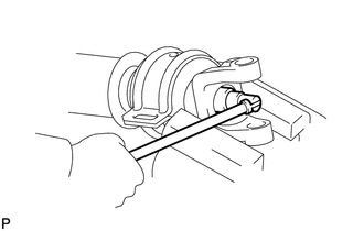
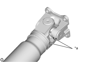
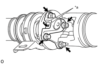
*a Hammering Point Using a hammer, tap the flange yoke until there is no clearance between the spider bearing outer race and snap ring.
Tech Tips
Install the spider bearing on the sleeve side using the procedure described above.
-
Align the matchmarks on the flange yoke and propeller shaft.
-
for Pre-Runner:
-
*a Matchmark w/ flange coupling:
Align the matchmarks on the flange yoke and propeller shaft.
-
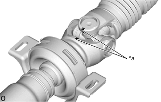
*a Matchmark w/o flange coupling:
Align the matchmarks on the center yoke and sleeve yoke.
-
*a Matchmark Align the matchmarks on the sleeve yoke and intermediate shaft.
-
-
for 4WD:
-
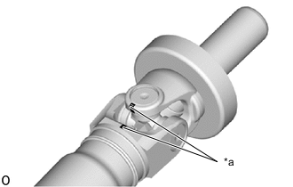
*a Matchmark w/ flange coupling:
Place matchmarks on the propeller shaft and flange yoke.
-
*a Matchmark w/o flange coupling:
Align the matchmarks on the center yoke and sleeve yoke.
-
*a Matchmark Align the matchmarks on the flange yoke and intermediate shaft.
-
-
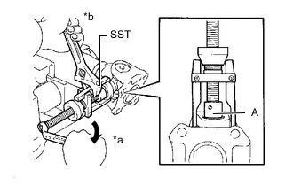
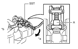
*a Turn *b Hold Using SST, install the 2 spider bearings to the spider.
- SST
- 09332-25010
Tech Tips
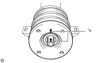
Before installing SST, sufficiently raise the part labeled A. If the part labeled A is too low, it may be difficult to install SST.
-
Using SST, adjust both spider bearings so that the front propeller shaft joint spider bearing snap ring grooves are as wide as possible and equal in width.
- SST
- 09332-25010
-
Install 2 new snap rings to the installed spider bearings. The snap rings must have equal thickness and allow 0 to 0.05 mm (0 to 0.00196 in.) of axial play.
Note
While the installed snap rings should have equal thickness, if the axial play is greater than 0.05 mm (0.00196 in.), select 2 snap rings that have as close to the same thickness as possible.
Tech Tips
Do not reuse the snap rings.
Standard Snap Ring Thickness (for Pre-Runner (w/ flange coupling)) Part No. Mark Thickness 90520-T0007 F 2.18 to 2.20 mm (0.0859 to 0.0866 in.) 90520-T0008 G 2.20 to 2.22 mm (0.0867 to 0.0874 in.) 90520-T0009 H 2.22 to 2.24 mm (0.0875 to 0.0881 in.) 90520-T0010 J 2.24 to 2.26 mm (0.0882 to 0.0889 in.) 90520-T0011 K 2.26 to 2.28 mm (0.0890 to 0.0897 in.) 90520-T0012 1 2.28 to 2.30 mm (0.0898 to 0.0905 in.) 90520-T0013 2 2.30 to 2.32 mm (0.0906 to 0.0913 in.) 90520-T0014 3 2.32 to 2.34 mm (0.0914 to 0.0921 in.) 90520-T0015 4 2.34 to 2.36 mm (0.0922 to 0.0929 in.) 90520-T0016 5 2.36 to 2.38 mm (0.0930 to 0.0937 in.) 90520-T0017 6 2.38 to 2.40 mm (0.0938 to 0.0944 in.) 90520-T0018 7 2.40 to 2.42 mm (0.0945 to 0.0952 in.) 90520-T0019 8 2.42 to 2.44 mm (0.0953 to 0.0960 in.) 90520-T0020 N 2.44 to 2.46 mm (0.0961 to 0.0968 in.) 90520-T0021 10 2.46 to 2.48 mm (0.0969 to 0.0976 in.) 90520-T0022 A 2.48 to 2.50 mm (0.0977 to 0.0984 in.) 90520-T0023 B 2.50 to 2.52 mm (0.0985 to 0.0992 in.) 90520-T0024 C 2.52 to 2.54 mm (0.0993 to 0.0999 in.) 90520-T0025 D 2.54 to 2.56 mm (0.1000 to 0.1007 in.) 90520-T0026 E 2.56 to 2.58 mm (0.1008 to 0.1015 in.) Standard Snap Ring Thickness (for Pre-Runner (w/o flange coupling)) Part No. Mark Thickness 90520-T0223 A 1.985 to 2.015 mm (0.0782 to 0.0793 in.) 90520-T0224 B 2.015 to 2.045 mm (0.0794 to 0.0805 in.) 90520-T0225 C 2.045 to 2.075 mm (0.0806 to 0.0816 in.) 90520-T0226 D 2.075 to 2.105 mm (0.0817 to 0.0828 in.) 90520-T0227 1 1.98 to 2.00 mm (0.0780 to 0.0787 in.) 90520-T0228 2 2.00 to 2.02 mm (0.0788 to 0.0795 in.) 90520-T0229 3 2.02 to 2.04 mm (0.0796 to 0.0803 in.) 90520-T0230 4 2.04 to 2.06 mm (0.0804 to 0.0811 in.) 90520-T0231 5 2.06 to 2.08 mm (0.0812 to 0.0818 in.) 90520-T0232 6 2.08 to 2.10 mm (0.0819 to 0.0826 in.) 90520-T0233 7 2.10 to 2.12 mm (0.0827 to 0.0834 in.) 90520-T0234 8 2.12 to 2.14 mm (0.0835 to 0.0842 in.) 90520-T0235 N 2.14 to 2.16 mm (0.0843 to 0.0850 in.) 90520-T0236 10 2.16 to 2.18 mm (0.0851 to 0.0858 in.) Standard Snap Ring Thickness (for 4WD (w/ flange coupling)) Part No. Mark Thickness 90520-T0007 F 2.18 to 2.20 mm (0.0859 to 0.0866 in.) 90520-T0008 G 2.20 to 2.22 mm (0.0867 to 0.0874 in.) 90520-T0009 H 2.22 to 2.24 mm (0.0875 to 0.0881 in.) 90520-T0010 J 2.24 to 2.26 mm (0.0882 to 0.0889 in.) 90520-T0011 K 2.26 to 2.28 mm (0.0890 to 0.0897 in.) 90520-T0012 1 2.28 to 2.30 mm (0.0898 to 0.0905 in.) 90520-T0013 2 2.30 to 2.32 mm (0.0906 to 0.0913 in.) 90520-T0014 3 2.32 to 2.34 mm (0.0914 to 0.0921 in.) 90520-T0015 4 2.34 to 2.36 mm (0.0922 to 0.0929 in.) 90520-T0016 5 2.36 to 2.38 mm (0.0930 to 0.0937 in.) 90520-T0017 6 2.38 to 2.40 mm (0.0938 to 0.0944 in.) 90520-T0018 7 2.40 to 2.42 mm (0.0945 to 0.0952 in.) 90520-T0019 8 2.42 to 2.44 mm (0.0953 to 0.0960 in.) 90520-T0020 N 2.44 to 2.46 mm (0.0961 to 0.0968 in.) 90520-T0021 10 2.46 to 2.48 mm (0.0969 to 0.0976 in.) 90520-T0022 A 2.48 to 2.50 mm (0.0977 to 0.0984 in.) 90520-T0023 B 2.50 to 2.52 mm (0.0985 to 0.0992 in.) 90520-T0024 C 2.52 to 2.54 mm (0.0993 to 0.0999 in.) 90520-T0025 D 2.54 to 2.56 mm (0.1000 to 0.1007 in.) 90520-T0026 E 2.56 to 2.58 mm (0.1008 to 0.1015 in.) Standard Snap Ring Thickness (for 4WD (w/o flange coupling)) for Vehicle Type A Part No. Mark Thickness 90520-T0007 F 2.18 to 2.20 mm (0.0859 to 0.0866 in.) 90520-T0008 G 2.20 to 2.22 mm (0.0867 to 0.0874 in.) 90520-T0009 H 2.22 to 2.24 mm (0.0875 to 0.0881 in.) 90520-T0010 J 2.24 to 2.26 mm (0.0882 to 0.0889 in.) 90520-T0011 K 2.26 to 2.28 mm (0.0890 to 0.0897 in.) 90520-T0012 1 2.28 to 2.30 mm (0.0898 to 0.0905 in.) 90520-T0013 2 2.30 to 2.32 mm (0.0906 to 0.0913 in.) 90520-T0014 3 2.32 to 2.34 mm (0.0914 to 0.0921 in.) 90520-T0015 4 2.34 to 2.36 mm (0.0922 to 0.0929 in.) 90520-T0016 5 2.36 to 2.38 mm (0.0930 to 0.0937 in.) 90520-T0017 6 2.38 to 2.40 mm (0.0938 to 0.0944 in.) 90520-T0018 7 2.40 to 2.42 mm (0.0945 to 0.0952 in.) 90520-T0019 8 2.42 to 2.44 mm (0.0953 to 0.0960 in.) 90520-T0020 N 2.44 to 2.46 mm (0.0961 to 0.0968 in.) 90520-T0021 10 2.46 to 2.48 mm (0.0969 to 0.0976 in.) 90520-T0022 A 2.48 to 2.50 mm (0.0977 to 0.0984 in.) 90520-T0023 B 2.50 to 2.52 mm (0.0985 to 0.0992 in.) 90520-T0024 C 2.52 to 2.54 mm (0.0993 to 0.0999 in.) 90520-T0025 D 2.54 to 2.56 mm (0.1000 to 0.1007 in.) 90520-T0026 E 2.56 to 2.58 mm (0.1008 to 0.1015 in.) for Vehicle Type B Part No. Mark Thickness 90520-T0223 A 1.985 to 2.015 mm (0.0782 to 0.0793 in.) 90520-T0224 B 2.015 to 2.045 mm (0.0794 to 0.0805 in.) 90520-T0225 C 2.045 to 2.075 mm (0.0806 to 0.0816 in.) 90520-T0226 D 2.075 to 2.105 mm (0.0817 to 0.0828 in.) 90520-T0227 1 1.98 to 2.00 mm (0.0780 to 0.0787 in.) 90520-T0228 2 2.00 to 2.02 mm (0.0788 to 0.0795 in.) 90520-T0229 3 2.02 to 2.04 mm (0.0796 to 0.0803 in.) 90520-T0230 4 2.04 to 2.06 mm (0.0804 to 0.0811 in.) 90520-T0231 5 2.06 to 2.08 mm (0.0812 to 0.0818 in.) 90520-T0232 6 2.08 to 2.10 mm (0.0819 to 0.0826 in.) 90520-T0233 7 2.10 to 2.12 mm (0.0827 to 0.0834 in.) 90520-T0234 8 2.12 to 2.14 mm (0.0835 to 0.0842 in.) 90520-T0235 N 2.14 to 2.16 mm (0.0843 to 0.0850 in.) 90520-T0236 10 2.16 to 2.18 mm (0.0851 to 0.0858 in.) Note
-
While the installed snap rings should have equal thickness, if the axial play is greater than 0.05 mm (0.00196in.), select 2 snap rings that have as close to the same thickness as possible.
-
Use a new snap ring.
-
Use a snap ring with as close to the same thickness as possible on both ends.
-
-
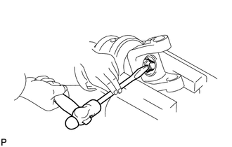
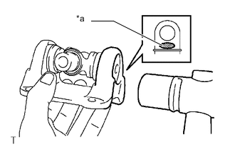
*a Hammering Point Using a hammer, tap the propeller shaft until there is no clearance between the spider bearing outer race and snap ring.
Tech Tips
Install the spider bearing on the sleeve side using the procedure described above.
-
w/ flange coupling:
-
Completely remove any oil, etc. and clean the contact surfaces of the flange coupling and flange yoke.
-
*a Matchmark Align the matchmarks on the flange yoke and flange coupling, and connect them with the 4 washers and 4 nuts.
- Torque:
- 88.2 N*m { 899 kgf*cm, 65 ft.*lbf }
Note
-
If any parts with matchmarks are replaced during inspection, reassemble them so that the sleeve yoke of the intermediate shaft and the rear flange yoke of the propeller shaft are at right angles to each other.
for Pre-Runner:
-
If any parts with matchmarks are replaced during inspection, reassemble them so that the front flange yoke of the intermediate shaft and the rear flange yoke of the propeller shaft are at right angles to each other.
for 4WD:
-
-
-
INSTALL REAR PROPELLER SHAFT BOOT CLAMP (for 4WD)
-
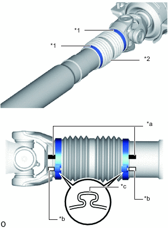
*1 Propeller Shaft Boot Clamp *2 Rear Sliding Shaft Boot *a Matchmark of Propeller Shaft and Sleeve Yoke *b Matchmark of Pinching Portion of Propeller Shaft Boot Clamp *c Pinching Portion Temporarily install a new rear sliding shaft boot to the propeller shaft with 2 new propeller shaft boot clamps.
-
Coat the splines of the propeller shaft with grease.
Standard Grease Capacity 27.5 to 32.5 g (0.97 to 1.14 oz) -
Align the matchmarks on the propeller shaft and sleeve yoke.
-
Install the sleeve yoke to the propeller shaft and connect the rear sliding shaft boot.
-
Align the matchmarks on the propeller shaft, sleeve yoke and the pinching portions of the 2 propeller shaft boot clamps.
Tech Tips
Make sure to align the matchmarks of the propeller shaft boot clamp.
If the pinching portions are installed at different locations than where they were located before disassembly, the rotational balance of the propeller shaft cannot be ensured, which may result in vibrations and noise.
-
Secure one of the propeller shaft boot clamps to the rear sliding shaft boot.
Tech Tips
-
Use the same procedure for each propeller shaft boot clamp.
-
Make sure that the matchmarks of the pinching portion of the propeller shaft boot clamp are aligned.
-
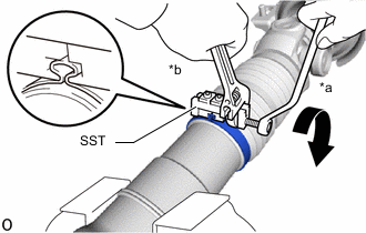
*a Turn *b Hold Install SST to the propeller shaft boot clamp, and then while pressing the rear sliding shaft boot, slightly tighten the SST bolt.
- SST
- 09521-24010
Note
-
Correctly set the propeller shaft boot clamp to the guide groove.
-
Do not damage the rear sliding shaft boot.
-
Tighten SST so that the propeller shaft boot clamp is pinched.
Standard clearance 3.8 mm (0.150 in.) or less Note
-
When tightening SST, make sure the clearance of the propeller shaft boot clamp is within the standard clearance.
-
Do not damage the rear sliding shaft boot.
-
-
Remove SST from the propeller shaft boot clamp.
-
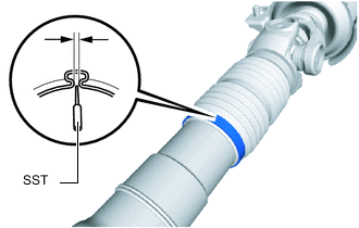
Using SST, measure the clearance of the propeller shaft boot clamp.
- SST
- 09240-00020
Standard clearance 3.8 mm (0.150 in.) or less Note
If the measured value exceeds the specified value, retighten the propeller shaft boot clamp.
-
-
-
INSPECT PROPELLER SHAFT GREASE FITTING DIRECTION
Tech Tips
-
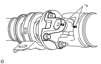
When replacing a spider bearing, be sure that the grease fitting hole is facing the direction shown in the illustration.
-
Fill the grease fittings with grease.
Grease Lithium base chassis grease NLGI No. 2
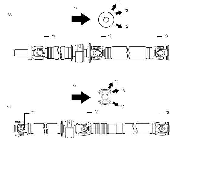
*A for Pre-Runner *B for 4WD *1 No. 1 Grease Fitting *2 No. 2 Grease Fitting *3 No. 3 Grease Fitting - - *a Rear Side - - -
-
INSPECT SPIDER BEARING