PROPELLER SHAFT ASSEMBLY(for TMMIN Made) DISASSEMBLY

CAUTION / NOTICE / HINT
Note
-
When using a vise, place aluminum plates between the part and vise.
-
When using a vise, do not overtighten it.
PROCEDURE
-
REMOVE REAR PROPELLER SHAFT BOOT CLAMP (for 4WD)
-
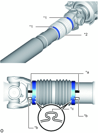
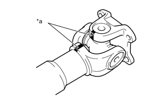
*1 Propeller Shaft Boot Clamp *2 Rear Sliding Shaft Boot *a Matchmark of Propeller Shaft and Sleeve Yoke *b Matchmark of Pinching Portion of Propeller Shaft Boot Clamp *c Pinching Portion Place matchmarks on the propeller shaft and sleeve yoke.
-
Apply matchmarks at the pinching portions of the propeller shaft boot clamps of the propeller shaft and sleeve yoke.
Tech Tips
-
Make sure to place matchmarks to clearly identify the location of the pinching portions of the propeller shaft boot clamps.
If the pinching portions are installed at different locations than where they were located before disassembly, the rotational balance of the propeller shaft cannot be ensured, which may result in vibrations and noise.
-
Make sure that the matchmarks are different enough so that they cannot be confused with each other.
-
The location of the pinching portions may differ from the location shown in the illustration, so make sure to confirm and properly place matchmarks according to the vehicle.
-
-
Using a side cutter or pliers, disconnect the 2 propeller shaft boot clamps.
-
Disconnect the 2 propeller shaft boot clamps from the sleeve yoke.
-
Remove the sleeve yoke, and then remove the rear sliding shaft boot and 2 propeller shaft boot clamps from the propeller shaft.
-
-
REMOVE SPIDER BEARING
Tech Tips
Use the same procedure for all spiders.
-
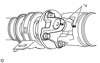
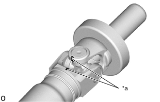
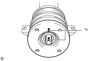
*a Matchmark Place matchmarks on the flange yoke and propeller shaft.
-
for Pre-Runner:
-
*a Matchmark w/ flange coupling:
Place matchmarks on the propeller shaft and flange yoke.
-
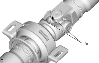
*a Matchmark w/o flange coupling:
Place matchmarks on the center yoke and sleeve yoke.
-
*a Matchmark Place matchmarks on the sleeve yoke and intermediate shaft.
-
-
for 4WD:
-
*a Matchmark w/ flange coupling:
Place matchmarks on the propeller shaft and flange yoke.
-
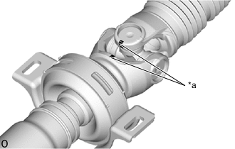
*a Matchmark w/o flange coupling:
Place matchmarks on the center yoke and sleeve yoke.
-
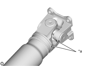
*a Matchmark Place matchmarks on the flange yoke and intermediate shaft.
-
-
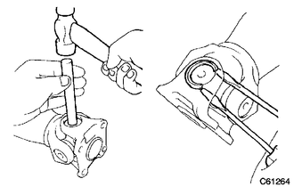
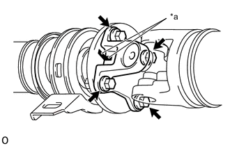
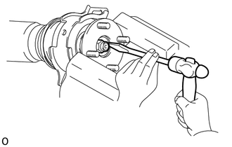
Using a brass bar and hammer, slightly tap in the spider bearing outer races.
-
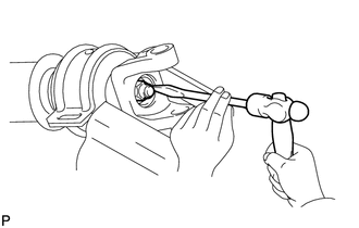
Using 2 screwdrivers, remove the 4 snap rings from the grooves.
-
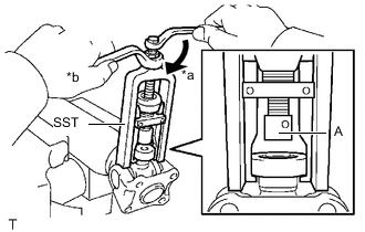
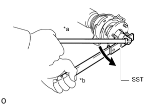
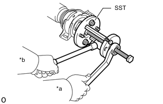
*a Turn *b Hold Using SST, push out the spider bearing from the propeller shaft assembly.
- SST
- 09332-25010
Tech Tips
Before installing SST, sufficiently raise the part labeled A. If the part labeled A is too low, it may be difficult to install SST.
-
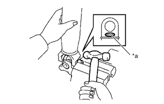
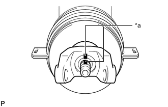
*a Hammering Point Tap off the propeller shaft to remove the spider bearing.
Note
Do not tap the shaft.
Tech Tips
Remove the spider bearing on the opposite side using the same procedure.
-
Remove the flange yoke from the propeller shaft.
-
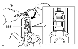
*a Turn *b Hold Install the 2 removed spider bearing outer races to the spider.
-
Using SST, push out the spider bearing from the flange yoke.
- SST
- 09332-25010
Tech Tips
Before installing SST, sufficiently raise the part labeled A. If the part labeled A is too low, it may be difficult to install SST.
-
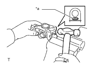
*a Hammering Point Tap off the spider bearing with a hammer.
-
Remove the spider.
-
-
REMOVE CENTER NO. 1 SUPPORT BEARING ASSEMBLY (for Pre-Runner)
-
w/ flange coupling:
-
*a Matchmark Place matchmarks on the flange coupling and flange yoke.
-
Remove the 4 nuts and 4 washers.
-
Disconnect the propeller shaft and intermediate shaft.
-
Using a chisel and hammer, loosen the staked part of the lock nut.
Note
-
Completely loosen the staked part of the lock nut when removing it.
-
Do not damage the threads of the intermediate shaft.
-
-
*a Turn *b Hold Using SST and a socket wrench, remove the lock nut.
- SST
- 09330-00021
-
*a Matchmark Place matchmarks on the intermediate shaft and flange coupling.
-
*a Turn *b Hold Using SST, remove the flange coupling and 2 washers from the intermediate shaft.
- SST
- 09950-30012 ( 09951-03010, 09953-03010, 09954-03010, 09955-03030, 09956-03030 )
-
Remove the center No. 1 support bearing assembly.
-
-
w/o flange coupling:
-
Using a hammer and chisel, loosen the staked part of the lock nut and remove the lock nut.
Note
-
Completely loosen the staked part of the lock nut when removing it.
-
Do not damage the threads of the intermediate shaft.
-
-
*a Matchmark Place matchmarks on the intermediate shaft and center yoke.
-
Using a brass bar and hammer, tap out the center yoke.
-
Remove the 2 washers and center No. 1 support bearing assembly from the intermediate shaft.
-
-
-
REMOVE CENTER NO. 1 SUPPORT BEARING ASSEMBLY (for 4WD)
-
w/ flange coupling:
-
*a Matchmark Place matchmarks on the flange coupling and flange yoke.
-
Remove the 4 nuts and 4 washers.
-
Disconnect the propeller shaft and intermediate shaft.
-
Using a chisel and hammer, loosen the staked part of the lock nut.
Note
-
Completely loosen the staked part of the lock nut when removing it.
-
Do not damage the threads of the intermediate shaft.
-
-
*a Turn *b Hold Using SST and a socket wrench, remove the lock nut.
- SST
- 09330-00021
-
*a Matchmark Place matchmarks on the intermediate shaft and flange coupling.
-
*a Turn *b Hold Using SST, remove the flange coupling and 2 washers from the intermediate shaft.
- SST
- 09950-30012 ( 09951-03010, 09953-03010, 09954-03010, 09955-03030, 09956-03030 )
-
Remove the center No. 1 support bearing assembly.
-
-
w/o flange coupling:
-
Using a hammer and chisel, loosen the staked part of the lock nut and remove the lock nut.
Note
-
Completely loosen the staked part of the lock nut when removing it.
-
Do not damage the threads of the intermediate shaft.
-
-
*a Matchmark Place matchmarks on the intermediate shaft and center yoke.
-
Using a brass bar and hammer, tap out the center yoke.
-
Remove the 2 washers and center No. 1 support bearing assembly from the intermediate shaft.
-
-