TOUCH SELECT 2-4 AND HIGH-LOW SYSTEM 4WD Control Switch Circuit
WIRING DIAGRAM
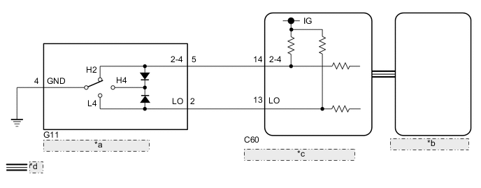
| *a | Transfer Position Switch |
| *b | Combination Meter Assembly |
| *c | 4 Wheel Drive Control ECU |
| *d | CAN Communication Line |
PROCEDURE
-
CONFIRM PROBLEM SYMPTOM
-
Confirm the problem symptoms.
Result Result Proceed to The 4WD indicator light (green) and 4LO indicator light remain off A The 4WD indicator light (green) remains illuminated, and the 4LO indicator light remains off B The 4WD indicator light (green) and 4LO indicator light remain illuminated C
B 
CHECK 4WD INDICATOR LIGHT (GREEN) Click here
C
CHECK 4LO INDICATOR LIGHT Click here
A 
-
-
CHECK 4WD INDICATOR LIGHT (GREEN)
-
Turn the ignition switch to ON.
-
for Automatic Transmission:
Move the shift lever to N.
for Manual Transmission:
Depress the clutch pedal.
-
Turn the transfer position switch to H4.
-
Wait for 60 seconds.
-
Check the 4WD indicator light (green).
Result Result Proceed to The 4WD indicator light (green) blinks*1 or illuminates A The 4WD indicator light (green) rapidly blinks*2 or remains off B
-
*1 (Blinking): Blinks at 0.5 second intervals (0.5 seconds on and 0.5 seconds off)
-
*2 (Rapidly blinking): Blinks at 0.25 second intervals (0.25 seconds on and 0.25 seconds off)
-
A 
END
B
-
-
CHECK FOR DTC
-
Turn the transfer position switch to L4.
-
Check if DTC P279E is output after 60 seconds elapse.
Result Result Proceed to DTC P279E is not output A DTC P279E is output B
B
REPAIR CIRCUIT INDICATED BY OUTPUT CODE Click here
A
-
-
CHECK CAN COMMUNICATION LINE
-
Select "Bus Check" from the System Selection Menu screen, and follow the prompts on the screen to inspect the CAN Bus.
OK "Bus Check" indicates no malfunctions in CAN communication. Result Proceed to OK NG
NG
CHECK CAN COMMUNICATION SYSTEM Click here
OK
-
-
CHECK TRANSFER POSITION SWITCH
-
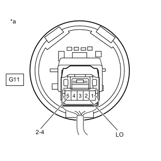
*a Component with harness connected
(Transfer Position Switch)
Remove the transfer position switch with its connector still connected.
-
Measure the voltage according to the value(s) in the table below.
Standard Voltage Tester Connection Switch Condition Specified Condition G11-5 (2-4) - Body ground Ignition switch ON
H2 position
Below 1.5 V Ignition switch ON
H4 position
Below 1.5 V Ignition switch ON
L4 position
10 to 14 V G11-2 (LO) - Body ground Ignition switch ON
H2 position
10 to 14 V Ignition switch ON
H4 position
Below 1.5 V Ignition switch ON
L4 position
Below 1.5 V Result Proceed to OK NG
OK
CHECK METER / GAUGE SYSTEM Click here
NG
REPLACE TRANSFER POSITION SWITCH Click here
-
-
CHECK 4WD INDICATOR LIGHT (GREEN)
-
Turn the ignition switch to ON.
-
for Automatic Transmission:
Move the shift lever to N.
for Manual Transmission:
Depress the clutch pedal.
-
Turn the transfer position switch to H2.
-
Wait for 60 seconds.
-
Check the 4WD indicator light (green).
Result Result Proceed to The 4WD indicator light (green) blinks*1 or turns off A The 4WD indicator light (green) rapidly blinks*2 or remains on B
-
*1 (Blinking): Blinks at 0.5 second intervals (0.5 seconds on and 0.5 seconds off)
-
*2 (Rapidly blinking): Blinks at 0.25 second intervals (0.25 seconds on and 0.25 seconds off)
-
A
END
B
GO TO DTC P279E Click here
-
-
CHECK 4LO INDICATOR LIGHT
Tech Tips
Perform the following procedures with the vehicle stopped.
-
Turn the ignition switch to ON.
-
for Automatic Transmission:
Move the shift lever to N.
for Manual Transmission:
Depress the clutch pedal.
-
Turn the transfer position switch to H4.
-
Wait for 60 seconds.
-
Check the 4LO indicator light.
Result Result Proceed to The 4LO indicator light blinks*1 or turns off A The 4LO indicator light rapidly blinks*2 or remains on B
-
*1 (Blinking): Blinks at 0.5 second intervals (0.5 seconds on and 0.5 seconds off)
-
*2 (Rapidly blinking): Blinks at 0.25 second intervals (0.25 seconds on and 0.25 seconds off)
-
A
END
B
-
-
CHECK FOR DTC
-
Turn the transfer position switch to H2.
-
Check if DTC P279E is output after 60 seconds elapse.
Result Result Proceed to DTC P279E is not output A DTC P279E is output B
B
REPAIR CIRCUIT INDICATED BY OUTPUT CODE Click here
A
-
-
CHECK TRANSFER POSITION SWITCH
-
*a Component with harness connected
(Transfer Position Switch)
Remove the transfer position switch with its connector still connected.
-
Measure the voltage according to the value(s) in the table below.
Standard Voltage Tester Connection Switch Condition Specified Condition G11-5 (2-4) - Body ground Ignition switch ON
H2 position
Below 1.5 V Ignition switch ON
H4 position
Below 1.5 V Ignition switch ON
L4 position
10 to 14 V G11-2 (LO) - Body ground Ignition switch ON
H2 position
10 to 14 V Ignition switch ON
H4 position
Below 1.5 V Ignition switch ON
L4 position
Below 1.5 V Result Proceed to OK NG
OK
CHECK CAN COMMUNICATION SYSTEM Click here
NG
REPLACE TRANSFER POSITION SWITCH Click here
-