TOUCH SELECT 2-4 AND HIGH-LOW SYSTEM TERMINALS OF ECU
-
CHECK 4 WHEEL DRIVE CONTROL ECU
-
Measure the resistance and voltage according to the value(s) in the table below.
Terminal No. (Symbol) Wiring Color Terminal Description Condition Specified Condition C60-1 (4WD) - C61-10 (GND) W - W-B 4WD detection switch signal input Ignition switch ON
Transfer position 2WD
10 to 14 V Ignition switch ON
Transfer position 4WD
Below 1.5 V C60-2 (ADD) - C61-10 (GND) W - W-B A.D.D. position switch input Ignition switch ON
Transfer position 2WD (A.D.D. actuator Free)
10 to 14 V Ignition switch ON
Transfer position 4WD (A.D.D. actuator Lock)
Below 1.5 V C60-3 (4WDL) - C61-10 (GND) Y - W-B L4 detection switch signal input Ignition switch ON
Transfer position not in L4
10 to 14 V Ignition switch ON
Transfer position L4
Below 1.5 V C60-5 (DT) - C60-25 (DGND) G - B Oil temperature sensor signal input Ignition switch ON 0.9 to 4.9 V C60-7 (DL2) - C61-10 (GND) B - W-B A.D.D. actuator limit switch input Ignition switch ON
Transfer position 2WD (A.D.D. actuator Free)
10 to 14 V Ignition switch ON
Transfer position 4WD (A.D.D. actuator Lock)
Below 1.5 V C60-8 (DL1) - C61-10 (GND) G - W-B A.D.D. actuator limit switch input Ignition switch ON
Transfer position 2WD (A.D.D. actuator Free)
Below 1.5 V Ignition switch ON
Transfer position 4WD (A.D.D. actuator Lock)
10 to 14 V C60-9 (TL3) - C61-10 (GND) W - W-B Transfer shift actuator limit switch input Ignition switch ON
TL3 terminal limit switch off (transfer H2 or L4)
10 to 14 V Ignition switch ON
TL3 terminal limit switch on (transfer H4)
Below 1.5 V C60-10 (TL2) - C61-10 (GND) G - W-B Transfer shift actuator limit switch input Ignition switch ON
TL2 terminal limit switch off (transfer H2 or H4)
10 to 14 V Ignition switch ON
TL2 terminal limit switch on (transfer L4)
Below 1.5 V C60-11 (TL1) - C61-10 (GND) L - W-B Transfer shift actuator limit switch input Ignition switch ON
TL1 terminal limit switch off (transfer H4 or L4)
10 to 14 V Ignition switch ON
TL1 terminal limit switch on (transfer H2)
Below 1.5 V C60-13 (LO) - C61-10 (GND) B - W-B Transfer position switch input Ignition switch ON
Transfer position switch H2
10 to 14 V Ignition switch ON
Transfer position switch H4
Below 1.5 V Ignition switch ON
Transfer position switch L4
Below 1.5 V C60-14 (2-4) - C61-10 (GND) L - W-B Transfer position switch input Ignition switch ON
Transfer position switch H2
Below 1.5 V Ignition switch ON
Transfer position switch H4
Below 1.5 V Ignition switch ON
Transfer position switch L4
10 to 14 V C60-18 (MTN) - C61-10 (GND)*2 L - W-B Clutch start switch input Ignition switch ON
Clutch pedal released
10 to 14 V Ignition switch ON
Clutch pedal depressed
Below 2 V C60-20 (CANH) - C60-40 (CANL) R - W HIGH-level CAN bus wire - LOW-level CAN bus wire Ignition switch off
Cable disconnected from negative (-) battery terminal
54 to 69 Ω C60-21 (+B) - C61-10 (GND) L - W-B ECU power supply Always 11 to 14 V C61-2 (DM1) - C61-10 (GND) W - W-B A. D. D. shift motor output Ignition switch ON
Transfer position switch H4 to H2
(during A.D.D. actuator Lock to Free operation)
Pulse generation
(see waveform 1)
C61-4 (IG) - C61-10 (GND) G - W-B ECU and actuator power supply Ignition switch ON 11 to 14 V C61-6 (DM2) - C61-10 (GND) R - W-B A. D. D. shift motor output Ignition switch ON
Transfer position switch H2 to H4
(during A.D.D. actuator Free to Lock operation)
Pulse generation
(see waveform 1)
C61-7 (TM2) - C61-10 (GND) Y - W-B Transfer shift motor output Ignition switch ON
Shift lever in N*1
Shift lever in neutral*2
Transfer position switch turned from H2 to H4 (switching from H2 to H4)
Transfer position switch turned from H4 to L4 (switching from H4 to L4)
Pulse generation
(see waveform 2)
C61-8 (TM1) - C61-10 (GND) B - W-B Transfer shift motor output Ignition switch ON
Shift lever in N*1
Shift lever in neutral*2
Transfer position switch turned from L4 to H4 (switching from L4 to H4)
Pulse generation
(see waveform 2)
C61-10 (GND) - Body ground W-B - Body ground Ground Always Below 1 Ω
-
*1: for Automatic Transmission
-
*2: for Manual Transmission
-
-
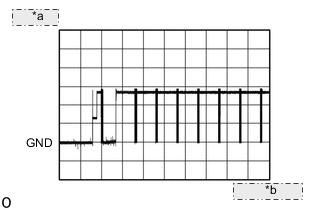
Waveform 1
-

*a 5 V/DIV. *b 100 ms./DIV. When a gear is engaged and switching is performed
Item Content Tester Connection C61-2 (DM1) - C61-10 (GND) Tool Setting 5 V/DIV., 100 ms./DIV. Condition Ignition switch ON
Transfer position switch H4 to H2
(during A.D.D. actuator Lock to Free operation)
Item Content Tester Connection C61-6 (DM2) - C61-10 (GND) Tool Setting 5 V/DIV., 100 ms./DIV. Condition Ignition switch ON
Transfer position switch H2 to H4
(during A.D.D. actuator Free to Lock operation)
-
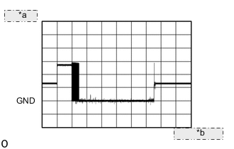
*a 5 V/DIV. *b 500 ms./DIV. When a gear is not engaged and switching is not performed
Item Content Tester Connection C61-2 (DM1) - C61-10 (GND) Tool Setting 5 V/DIV., 500 ms./DIV. Condition Ignition switch ON
Transfer position switch H4 to H2
(during A.D.D. actuator Lock to Free operation)
Item Content Tester Connection C61-6 (DM2) - C61-10 (GND) Tool Setting 5 V/DIV., 500 ms./DIV. Condition Ignition switch ON
Transfer position switch H2 to H4
(during A.D.D. actuator Free to Lock operation)
-
-
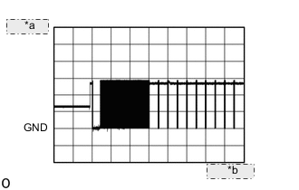
Waveform 2
-
*a 5 V/DIV. *b 100 ms./DIV. When a gear is engaged and switching is performed
Item Content Tester Connection C61-8 (TM1) - C61-10 (GND) Tool Setting 5 V/DIV., 100 ms./DIV. Condition Ignition switch ON
Shift lever in N*1
Shift lever in neutral*2
Transfer position switch turned from L4 to H4 (switching from L4 to H4)
-
*1: for Automatic Transmission
-
*2: for Manual Transmission
Item Content Tester Connection C61-7 (TM2) - C61-10 (GND) Tool Setting 5 V/DIV., 100 ms./DIV. Condition Ignition switch ON
Shift lever in N*1
Shift lever in neutral*2
Transfer position switch turned from H2 to H4 (switching from H2 to H4)
Transfer position switch turned from H4 to L4 (switching from H4 to L4)
-
*1: for Automatic Transmission
-
*2: for Manual Transmission
-
-
*a 5 V/DIV. *b 1 s./DIV. When a gear is not engaged and switching is not performed
Item Content Tester Connection C61-8 (TM1) - C61-10 (GND) Tool Setting 5 V/DIV., 1 s./DIV. Condition Ignition switch ON
Shift lever in N*1
Shift lever in neutral*2
Transfer position switch turned from L4 to H4 (switching from L4 to H4)
-
*1: for Automatic Transmission
-
*2: for Manual Transmission
Item Content Tester Connection C61-7 (TM2) - C61-10 (GND) Tool Setting 5 V/DIV., 1 s./DIV. Condition Ignition switch ON
Shift lever in N*1
Shift lever in neutral*2
Transfer position switch turned from H2 to H4 (switching from H2 to H4)
Transfer position switch turned from H4 to L4 (switching from H4 to L4)
-
*1: for Automatic Transmission
-
*2: for Manual Transmission
-
-
-