TRANSFER ASSEMBLY INSPECTION

PROCEDURE
-
INSPECT TRANSFER INPUT SHAFT
-
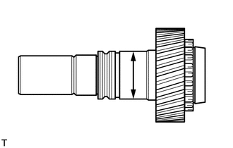
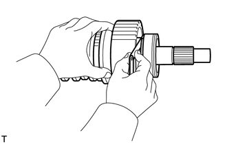
Using a micrometer, measure the diameter of the transfer input shaft journal surface.
Minimum diameter 47.59 mm (1.874 in.) If the diameter is less than the minimum, replace the transfer input shaft.
-
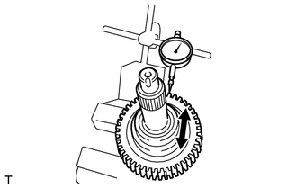
Using a dial indicator, measure the inside diameter of the transfer input shaft bushing.
Maximum inside diameter 39.14 mm (1.540 in.) If the inside diameter is more than the maximum, replace the transfer input shaft.
-
-
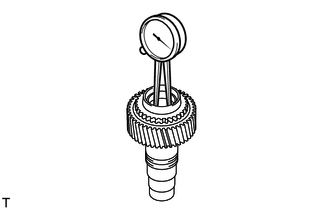
INSPECT TRANSFER LOW PLANETARY GEAR ASSEMBLY
-
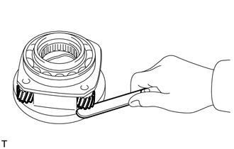
Using a feeler gauge, measure the thrust clearance of the pinion gear.
Standard clearance 0.11 to 0.84 mm (0.00434 to 0.0330 in.) Maximum clearance 0.84 mm (0.0330 in.) If the clearance is more than the maximum, replace the transfer low planetary gear assembly.
-
Using a dial indicator, measure the radial clearance of the pinion gear.
Standard clearance 0.009 to 0.038 mm (0.000355 to 0.00149 in.) Maximum clearance 0.038 mm (0.00149 in.) If the clearance is more than the maximum, replace the transfer low planetary gear assembly.
-
-
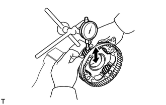
INSPECT TRANSFER DRIVE SPROCKET SUB-ASSEMBLY
-
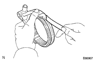
Using a feeler gauge, measure the thrust clearance.
Standard clearance 0.10 to 0.25 mm (0.00394 to 0.00984 in.) Maximum clearance 0.25 mm (0.00984 in.) If the thrust clearance is more than the maximum, replace the transfer drive sprocket sub-assembly.
-
Using a dial indicator, measure the radial clearance between the drive sprocket and output shaft with the needle roller bearing installed.
Standard radial clearance 0.010 to 0.055 mm (0.000394 to 0.00216 in.) Maximum radial clearance 0.055 mm (0.00216 in.) If the radial clearance is more than the maximum, replace the transfer drive sprocket sub-assembly or needle roller bearing.
-
-
INSPECT REAR TRANSFER OUTPUT SHAFT
-
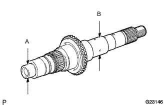
Using a micrometer, measure the diameter of the rear transfer output shaft journal surface.
Minimum diameter Journal Diameter A 27.98 mm (1.102 in.) B 36.98 mm (1.456 in.) If the diameter is less than the minimum, replace the rear transfer output shaft.
-
-
INSPECT FRONT DRIVE CLUTCH SLEEVE AND NO. 1 TRANSFER GEAR SHIFT FORK CLEARANCE
-
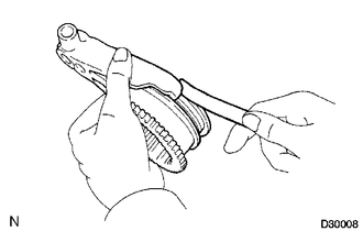
Using a feeler gauge, measure the clearance between the front drive clutch sleeve and No. 1 transfer gear shift fork.
Maximum clearance 0.35 mm (0.0137 in.) If the clearance is more than the maximum, replace the front drive clutch sleeve or No. 1 transfer gear shift fork.
-
-
INSPECT TRANSFER HIGH AND LOW CLUTCH SLEEVE AND NO. 2 TRANSFER GEAR SHIFT FORK CLEARANCE
-
Using a feeler gauge, measure the clearance between the transfer high and low clutch sleeve and No. 2 transfer gear shift fork.
Maximum clearance 0.35 mm (0.0137 in.) If the clearance is more than the maximum, replace the transfer high and low clutch sleeve or No. 2 transfer gear shift fork.
-
-
INSPECT TRANSFER SHIFT ACTUATOR ASSEMBLY
-
Inspect the transfer shift actuator assembly.
Note
-
Perform this inspection with the actuator removed from the vehicle.
If this inspection is performed with the actuator installed to the vehicle, the actuator will be damaged.
-
When inspecting the actuator, operate it with the lines connected via a relay.
If the lines are not connected via a relay and battery voltage is directly applied to the actuator, the actuator will be damaged.
Tech Tips
-
When inspecting the transfer shift actuator assembly, refer to the wiring diagram.
-
When performing the operation described above, use the DEF relay.
-
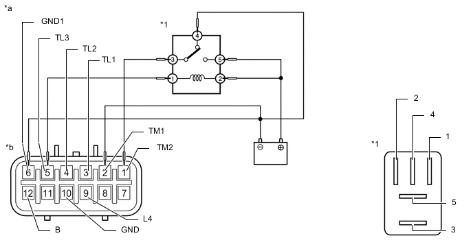
Check the 2WD to 4WD HIGH switch.
Connect lines via a relay as shown in the illustration, then check that the actuator fork moves from the 2WD to 4WD HIGH position.
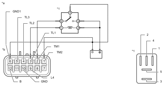
*1 DEF Relay - - *a 2WD to 4WD HIGH *b Component without harness connected
(Transfer Shift Actuator Assembly)
-
After the 2WD to 4WD HIGH switch is complete, inspect the 4WD detection switch, L4 detection switch and limit switch.
Standard Resistance Tester Connection Switch Condition Specified Condition 3 (TL1) - 6 (GND1) After 2WD to 4WD HIGH switch is complete 10 kΩ or higher 4 (TL2) - 6 (GND1) After 2WD to 4WD HIGH switch is complete 10 kΩ or higher 5 (TL3) - 6 (GND1) After 2WD to 4WD HIGH switch is complete Below 1 Ω 9 (L4) - 6 (GND1) After 2WD to 4WD HIGH switch is complete 10 kΩ or higher 12 (B) - 10 (GND) After 2WD to 4WD HIGH switch is complete Below 1 Ω
If the result is not as specified, replace the transfer shift actuator assembly.
-
-
Check the 4WD HIGH to 4WD LOW switch.
Connect lines via a relay as shown in the illustration, then check that the actuator fork moves from the 4WD HIGH to 4WD LOW position.
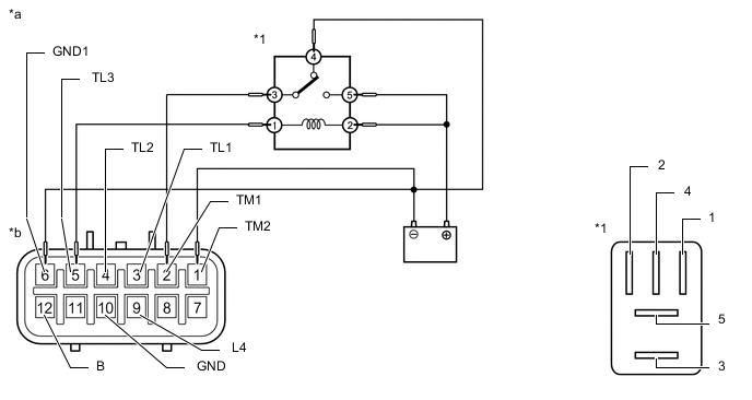
*1 DEF Relay - - *a 4WD HIGH to 4WD LOW *b Component without harness connected
(Transfer Shift Actuator Assembly)
-
After the 4WD HIGH to 4WD LOW switch is complete, inspect the 4WD detection switch, L4 detection switch and limit switch.
Standard Resistance Tester Connection Switch Condition Specified Condition 3 (TL1) - 6 (GND1) After 4WD HIGH to 4WD LOW switch is complete 10 kΩ or higher 4 (TL2) - 6 (GND1) After 4WD HIGH to 4WD LOW switch is complete Below 1 Ω 5 (TL3) - 6 (GND1) After 4WD HIGH to 4WD LOW switch is complete 10 kΩ or higher 9 (L4) - 6 (GND1) After 4WD HIGH to 4WD LOW switch is complete Below 1 Ω 12 (B) - 10 (GND) After 4WD HIGH to 4WD LOW switch is complete Below 1 Ω
If the result is not as specified, replace the transfer shift actuator assembly.
-
-
Check the 4WD LOW to 4WD HIGH switch.
Connect lines via a relay as shown in the illustration, then check that the actuator fork moves from the 4WD LOW to 4WD HIGH position.
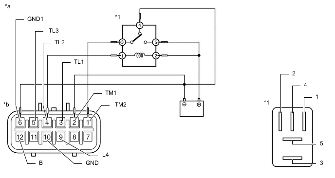
*1 DEF Relay - - *a 4WD LOW to 4WD HIGH *b Component without harness connected
(Transfer Shift Actuator Assembly)
-
After the 4WD LOW to 4WD HIGH switch is complete, inspect the 4WD detection switch, L4 detection switch and limit switch.
Standard Resistance Tester Connection Switch Condition Specified Condition 3 (TL1) - 6 (GND1) After 4WD LOW to 4WD HIGH switch is complete 10 kΩ or higher 4 (TL2) - 6 (GND1) After 4WD LOW to 4WD HIGH switch is complete 10 kΩ or higher 5 (TL3) - 6 (GND1) After 4WD LOW to 4WD HIGH switch is complete Below 1 Ω 9 (L4) - 6 (GND1) After 4WD LOW to 4WD HIGH switch is complete 10 kΩ or higher 12 (B) - 10 (GND) After 4WD LOW to 4WD HIGH switch is complete Below 1 Ω
If the result is not as specified, replace the transfer shift actuator assembly.
-
-
Check the 4WD HIGH to 2WD switch.
Connect lines via a relay as shown in the illustration, then check that the actuator fork moves from the 4WD HIGH to 2WD position.
*1 DEF Relay - - *a 4WD HIGH to 2WD *b Component without harness connected
(Transfer Shift Actuator Assembly)
-
After the 4WD HIGH to 2WD switch is complete, inspect the 4WD detection switch, L4 detection switch and limit switch.
Standard Resistance Tester Connection Switch Condition Specified Condition 3 (TL1) - 6 (GND1) After 4WD HIGH to 2WD switch is complete Below 1 Ω 4 (TL2) - 6 (GND1) After 4WD HIGH to 2WD switch is complete 10 kΩ or higher 5 (TL3) - 6 (GND1) After 4WD HIGH to 2WD switch is complete 10 kΩ or higher 9 (L4) - 6 (GND1) After 4WD HIGH to 2WD switch is complete 10 kΩ or higher 12 (B) - 10 (GND) After 4WD HIGH to 2WD switch is complete 10 kΩ or higher
If the result is not as specified, replace the transfer shift actuator assembly.
-
-
-