COUNTER GEAR REASSEMBLY

PROCEDURE
-
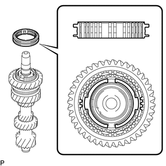
INSTALL 2ND GEAR NEEDLE ROLLER BEARING
-
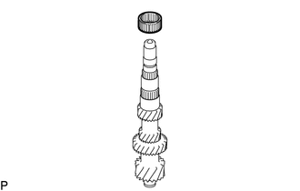
Coat the 2nd gear needle roller bearing with gear oil, and then install it to the counter gear.
-
-
INSTALL COUNTERSHAFT 2ND SPEED GEAR
-
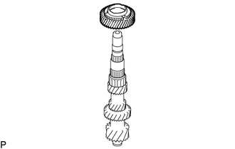
Coat the countershaft 2nd speed gear with gear oil, and then install it to the counter gear.
-
-
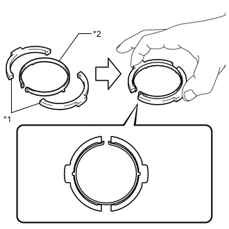
INSTALL NO. 2 SYNCHRONIZER RING SET
-
Coat the No. 2 synchronizer ring with gear oil.
-
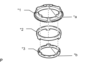
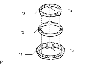
*1 No. 2 Synchronizer Ring (Outer Rring) *2 No. 2 Synchronizer Ring (Middle Ring) *3 No. 2 Synchronizer Ring (Inner Ring) *a Protrusion *b Cutout Align the 3 synchronizer rings as shown in the illustration.
Note
Align the protrusion of the No. 2 synchronizer inner ring with the cutout of the No. 2 synchronizer outer ring.
-
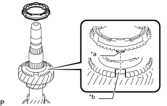
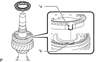
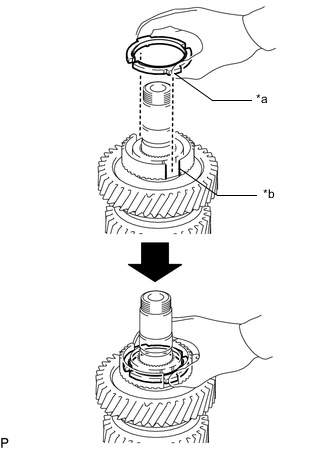
*1 Protrusion *2 Groove Install the No. 2 synchronizer ring set to the countershaft 2nd speed gear.
Note
Align the protrusion of the No. 2 synchronizer middle ring with the groove of the 2nd gear.
-
-
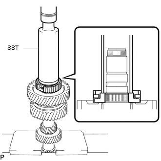
INSTALL NO. 1 TRANSMISSION CLUTCH HUB
-
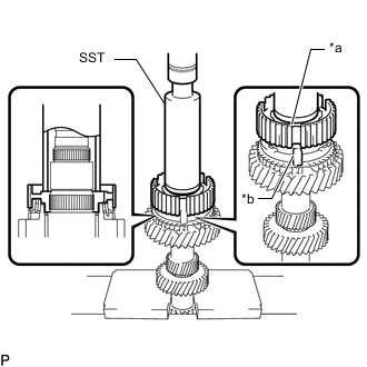
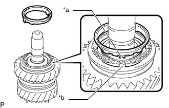
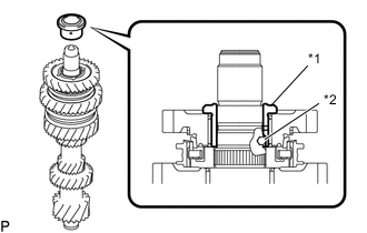
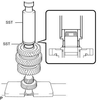
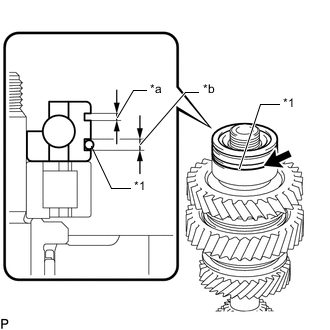
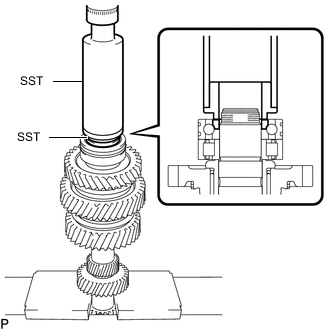
*a Groove *b Protrusion Using SST and a press, install the No. 1 transmission clutch hub to the counter gear.
- SST
- 09316-60011
Note
Align the groove of the No. 1 transmission clutch hub with the protrusion of the No. 2 synchronizer ring set.
Note
-
Pay attention to the installation direction of the No. 1 transmission clutch hub.
-
Align the groove of the No. 1 transmission clutch hub with the protrusion of the No. 2 synchronizer ring set.
-
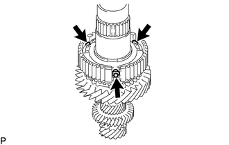
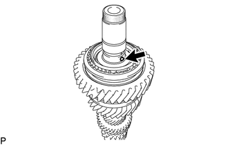
Check that the countershaft 2nd speed gear and No. 2 synchronizer ring set move smoothly.
-
-
INSTALL NO. 1 CLUTCH HUB SHAFT SNAP RING
-
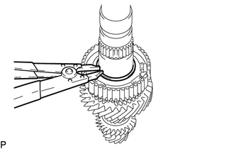
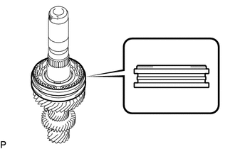
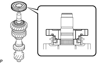
Select a new No. 1 clutch hub shaft snap ring that will allow minimal axial play.
Standard clearance 0.1 mm (0.00394 in.) or less Standard Snap Ring Part No. Mark Thickness 90520-T0168 A 2.28 to 2.33 mm (0.0898 to 0.0917 in.) 90520-T0169 B 2.33 to 2.38 mm (0.0918 to 0.0937 in.) 90520-T0170 C 2.38 to 2.43 mm (0.0938 to 0.0956 in.) 90520-T0171 D 2.43 to 2.48 mm (0.0957 to 0.0976 in.) 90520-T0172 E 2.48 to 2.53 mm (0.0977 to 0.0996 in.) 90520-T0173 F 2.53 to 2.58 mm (0.0997 to 0.1015 in.) -
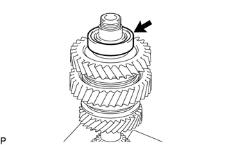
Using a snap ring expander, install the No. 1 clutch hub shaft snap ring to the counter gear.
-
-
INSTALL NO. 1 SYNCHROMESH SHIFTING KEY
-
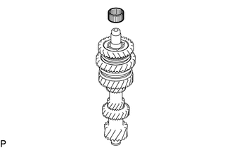
Install the 3 No. 1 synchromesh shifting keys to the No. 1 transmission clutch hub.
-
-
INSTALL NO. 1 TRANSMISSION HUB SLEEVE
-
Install the No. 1 transmission clutch hub to the No. 1 transmission clutch hub sleeve.
Note
Pay attention to the installation direction of the No. 1 transmission hub sleeve.
-
-
INSTALL NO. 1 SYNCHRONIZER RING SET
-
Coat the No. 2 synchronizer ring with gear oil.
-
*1 No. 1 Synchronizer Ring (Outer Ring) *2 No. 1 Synchronizer Ring (Middle Ring) *3 No. 1 Synchronizer Ring (Inner Ring) *a Protrusion *b Cutout Align the 3 synchronizer rings as shown in the illustration.
Note
Align the protrusion of the No. 1 synchronizer inner ring with the cutout of the No. 1 synchronizer outer ring.
-
*1 Protrusion *2 Groove Install the No. 1 synchronizer ring set to the No. 1 transmission clutch hub.
Note
Align the protrusion of the No. 1 synchronizer outer ring with the groove of the No. 1 transmission clutch hub.
-
-
INSTALL 1ST GEAR NEEDLE ROLLER BEARING
-
Coat the 1st gear needle roller bearing with gear oil, and then install it to the counter gear.
-
-
INSTALL COUNTERSHAFT 1ST SPEED GEAR
-
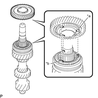
*a Groove *b Protrusion Coat the countershaft 1st speed gear with gear oil and install it to the counter gear.
Tech Tips
Align the groove of the countershaft 1st speed gear with the protrusion of the No. 1 synchronizer ring set.
-
-
INSTALL NO. 4 TRANSMISSION CLUTCH HUB
-
Coat the No. 4 transmission clutch hub with gear oil and install it to the counter gear.
-
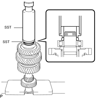
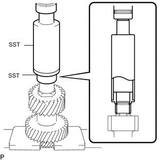
Using SST and a press, install the No. 4 transmission clutch hub.
- SST
- 09316-60011
-
-
INSTALL NO. 3 SYNCHROMESH SHIFTING KEY
-
Install No. 3 synchromesh shifting key.
-
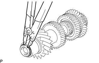
*1 No. 3 Synchromesh Shifting Key *2 No. 3 Synchromesh Shifting Key Spring Pinch and lift up the part as shown in the illustration.
Tech Tips
Refer to the illustration when installing the No. 3 synchromesh shifting key.
-
*a Protrusion *b Groove Install the part to the No. 4 transmission clutch hub as shown in the illustration.
Tech Tips
Align the groove of the No. 4 transmission sleeve hub with the protrusion of the No. 3 synchromesh shifting key.
-
-
-
INSTALL NO. 4 TRANSMISSION HUB SLEEVE
-
Coat the No. 4 transmission hub sleeve with gear oil and install it to the No. 4 transmission clutch hub.
Note
Pay attention to the installation direction of the No. 4 transmission hub sleeve.
-
-
INSTALL REVERSE SYNCHRONIZER RING
-
Coat the reverse synchronizer ring with gear oil.
-
*a Protrusion *b Groove Install the reverse synchronizer ring to the No. 4 transmission clutch hub.
Tech Tips
Align the groove of the No. 4 transmission hub with the protrusion of the reverse synchronizer ring.
-
-
INSTALL REVERSE SHIFT RESTRICT BALL
-
Install the reverse shift restrict ball to the counter gear.
-
-
INSTALL COUNTERSHAFT REVERSE GEAR
-
Coat the countershaft reverse gear with gear oil and install it to the counter gear.
Tech Tips
Refer to the illustration when installing the countershaft reverse gear.
-
-
INSTALL REVERSE GEAR BEARING
-
Coat the reverse gear bearing with gear oil, and then install it to the counter gear.
-
-
INSTALL REVERSE GEAR BEARING INNER RACE
-
*1 Reverse Gear Bearing Inner Race *2 Reverse Shift Restrict Ball Align the groove of the reverse gear bearing inner race with the reverse shift restrict ball and install the reverse gear bearing inner race.
-
-
INSTALL CENTER COUNTERSHAFT BEARING
-
Using SST and a press, install the center countershaft bearing (inner race) to the counter gear.
- SST
- 09316-60011 ( 09316-00011, 09316-00071 )
-
Coat the center countershaft bearing (outer race) with gear oil, and then install it to the center countershaft bearing (inner race).
-
-
INSTALL FRONT COUNTER GEAR BEARING OR ROLLER
-
Using SST and a press, install the front counter gear bearing or roller (inner race) to the counter gear.
- SST
- 09316-60011 ( 09316-00011, 09316-00071 )
-
*1 O-ring *a 2.28 to 2.48 mm (0.090 to 0.097 in.) *b 2.85 to 3.05 mm (0.113 to 0.120 in.) 
Gear Oil Coat the front counter gear bearing or roller (outer race) with gear oil, and then install it to the front counter gear bearing or roller (inner race).
-
Using SST and a press, install the front counter gear bearing or roller (inner race) to the counter gear.
- SST
- 09316-60011 ( 09316-00011, 09316-00071 )
-
-
INSTALL REAR COUNTER GEAR BEARING OR ROLLER
-
Using SST and a press, install the rear counter gear bearing or roller (inner race) to the counter gear.
- SST
- 09316-60011 ( 09316-00011, 09316-00071 )
-
-
INSTALL REAR COUNTER GEAR BEARING SNAP RING
-
Select a new rear counter gear bearing snap ring that will allow minimal axial play.
Standard clearance 0.1 mm (0.00394 in.) or less Standard Snap Ring Part No. Mark Thickness 90520-T0175 A 2.45 to 2.50 mm (0.0965 to 0.0984 in.) 90520-T0176 B 2.50 to 2.55 mm (0.0985 to 0.1003 in.) 90520-T0177 C 2.55 to 2.60 mm (0.1004 to 0.1023 in.) 90520-T0178 D 2.60 to 2.65 mm (0.1024 to 0.1043 in.) 90520-T0179 E 2.65 to 2.70 mm (0.1044 to 0.1062 in.) 90520-T0180 F 2.70 to 2.75 mm (0.1063 to 0.1082 in.) 90520-T0181 G 2.75 to 2.80 mm (0.1083 to 0.1102 in.) -
Using a snap ring expander, install the counter gear rear bearing snap ring to the counter gear.
-
-
INSPECT COUNTERSHAFT REVERSE GEAR THRUST CLEARANCE
-
INSPECT COUNTERSHAFT REVERSE GEAR RADIAL CLEARANCE
-
INSPECT COUNTERSHAFT 1ST SPEED GEAR THRUST CLEARANCE
-
INSPECT COUNTERSHAFT 1ST SPEED GEAR RADIAL CLEARANCE
-
INSPECT COUNTERSHAFT 2ND SPEED GEAR THRUST CLEARANCE
-
INSPECT COUNTERSHAFT 2ND SPEED GEAR RADIAL CLEARANCE