MANUAL TRANSMISSION ASSEMBLY INSTALLATION

PROCEDURE
-
INSTALL EXTENSION HOUSING DUST DEFLECTOR
-
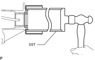
Using SST and hammer, tap in the extension housing dust deflector.
- SST
- 09513-36040
-
-
INSTALL WIRING HARNESS CLAMP BRACKET
-
w/ Intelligent Manual Transmission Switch:
-
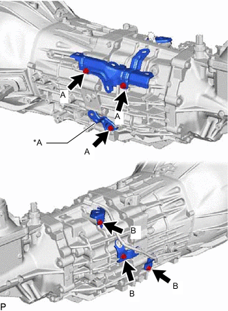
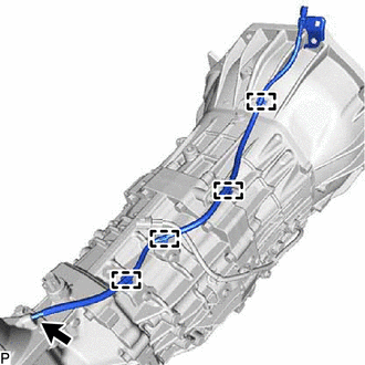
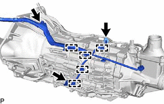
*A w/ Intelligent Manual Transmission Switch Install the 5 wiring harness clamp brackets to the manual transmission assembly with the 6 bolts.
- Torque:
- for bolt A
- 13 N*m { 133 kgf*cm, 10 ft.*lbf }
- for bolt B
- 12.6 N*m { 128 kgf*cm, 9 ft.*lbf }
-
-
w/o Intelligent Manual Transmission Switch:
-
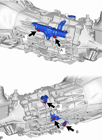
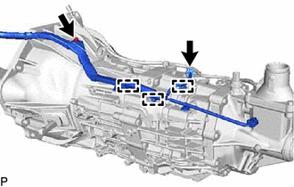
Install the 4 wiring harness clamp brackets to the manual transmission assembly with the 5 bolts.
- Torque:
- for bolt A
- 13 N*m { 133 kgf*cm, 10 ft.*lbf }
- for bolt B
- 12.6 N*m { 128 kgf*cm, 9 ft.*lbf }
-
-
-
INSTALL TRANSMISSION BREATHER SUB-ASSEMBLY
-
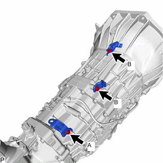
Install the 3 brackets to the manual transmission assembly with the 3 bolts.
- Torque:
- for bolt A
- 12.6 N*m { 128 kgf*cm, 9 ft.*lbf }
- for bolt B
- 19.0 N*m { 194 kgf*cm, 14 ft.*lbf }
-
Install the transmission breather sub-assembly to the control shift lever retainer sub-assembly.
-
Attach the 4 breather hose clamps.
-
-
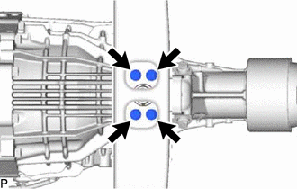
INSTALL MANUAL TRANSMISSION ASSEMBLY
-
Install the manual transmission assembly with the 5 bolts.
- Torque:
- 71.5 N*m { 729 kgf*cm, 53 ft.*lbf }
-
-
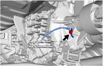
CONNECT WIRE HARNESS
-
w/ Intelligent Manual TransmissionSwitch
-
Connect the 2 connector.
-
Install the bolt.
- Torque:
- 13 N*m { 133 kgf*cm, 10 ft.*lbf }
-
Attach the 5 wire harness clamps.
-
-
w/o Intelligent Manual TransmissionSwitch
-
Connect the connector.
-
Install the bolt.
- Torque:
- 13 N*m { 133 kgf*cm, 10 ft.*lbf }
-
Attach the 3 wire harness clamps.
-
-
-
INSTALL REAR ENGINE MOUNTING INSULATOR
-
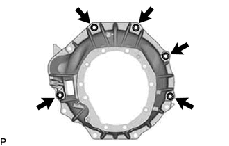
Install the rear engine mounting insulator to the manual transmission assembly with the 4 bolts.
- Torque:
- 47 N*m { 479 kgf*cm, 35 ft.*lbf }
-
-
INSTALL NO. 3 FRAME CROSSMEMBER SUB-ASSEMBLY
-
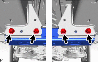
Install the No. 3 frame crossmember sub-assembly with the 4 nuts and 4 bolts.
- Torque:
- 57 N*m { 581 kgf*cm, 42 ft.*lbf }
-
Install the 4 bolts to the No. 3 frame crossmember sub-assembly.
- Torque:
- 18.5 N*m { 189 kgf*cm, 14 ft.*lbf }
-
-
CONNECT GROUND CABLE
-
Connect the ground cable with the bolt.
- Torque:
- 19.5 N*m { 199 kgf*cm, 14 ft.*lbf }
-
-
INSTALL PROPELLER SHAFT WITH CENTER BEARING ASSEMBLY
-
for TSAM Made:
-
for TMT Made:
-
for TMMIN Made:
-
-
INSTALL STIFFENER PLATE LH
-
Install the stiffener plate LH with the 4 bolts.
- Torque:
- 71.5 N*m { 729 kgf*cm, 53 ft.*lbf }
-
-
INSTALL STIFFENER PLATE RH
-
Install the stiffener plate RH with the 4 bolts.
- Torque:
- 71.5 N*m { 729 kgf*cm, 53 ft.*lbf }
-
-
INSTALL NO. 4 CYLINDER BLOCK INSULATOR
-
Install the No. 4 cylinder block insulator.
-
-
INSTALL STARTER ASSEMBLY (for 1GD-FTV)
-
for 2.0 kW Type:
-
for BOSCH Made:
-
-
INSTALL STARTER ASSEMBLY (for 2GD-FTV)
-
for 2.0 kW Type:
-
for BOSCH Made:
-
for 2.2 kW Type:
-
-
INSTALL CLUTCH RELEASE CYLINDER ASSEMBLY
-
INSTALL FRONT EXHAUST PIPE ASSEMBLY (for 1GD-FTV)
-
INSTALL FRONT EXHAUST PIPE ASSEMBLY (for 2GD-FTV)
-
INSTALL NO. 2 ENGINE UNDER COVER
-
INSTALL NO. 1 ENGINE UNDER COVER ASSEMBLY
-
ADD MANUAL TRANSMISSION OIL
-
INSTALL NO. 1 FLOOR SHIFT BUSH
-
Install the No. 1 floor shift bush to the floor shift shift lever assembly.
-
-
INSTALL SHIFT LEVER ASSEMBLY
-
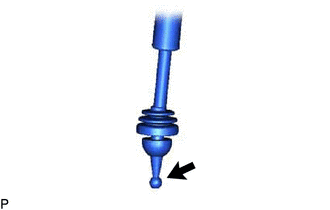

MP grease Apply MP grease to the tip of the shift lever assembly.
-
Cover the shift lever cap with a cloth.
-
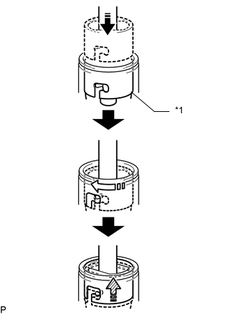
*1 Shift Lever Cap 
Press down 
Clockwise 
Lock While pressing down on the shift lever cap, turn it clockwise to install the shift lever assembly.
-
-
INSTALL SHIFT LEVER BOOT ASSEMBLY
-
Install the shift lever boot assembly with the 6 screws and 4 clips.
-
-
INSTALL CONSOLE BOX ASSEMBLY
-
CONNECT CABLE TO NEGATIVE BATTERY TERMINAL
Note
When disconnecting the cable, some systems need to be initialized after the cable is reconnected.